
MECHANICS OF MATERIALS
11th Edition
ISBN: 9780137605385
Author: HIBBELER
Publisher: PEARSON
expand_more
expand_more
format_list_bulleted
Concept explainers
Videos
Textbook Question
Chapter 14.3, Problem 31P
Determine the vertical displacement of point S on the A992 steel beam. I = 80(106) mm4.
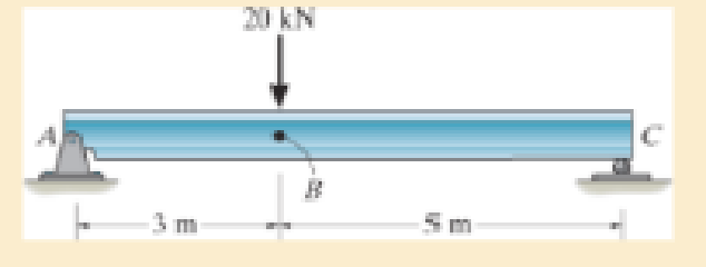
Prob. 14–31
Expert Solution & Answer
Want to see the full answer?
Check out a sample textbook solution
Students have asked these similar questions
The gears shown in the figure have a diametral pitch of 2 teeth per inch and a 20° pressure angle.
The pinion rotates at 1800 rev/min clockwise and transmits 200 hp through the idler pair to gear
5 on shaft c. What forces do gears 3 and 4 transmit to the idler shaft?
TS
I
y
18T
32T
This
a
12
x
18T
C
48T
5
Question 1. Draw 3 teeth for the following pinion and gear respectively. The teeth
should be drawn near the pressure line so that the teeth from the pinion should
mesh those of the gear. Drawing scale (1:1). Either a precise hand drawing or
CAD drawing is acceptable. Draw all the trajectories of the involute lines and the
circles.
Specification: 18tooth pinion and 30tooth gear. Diameter pitch=P=6 teeth /inch.
Pressure angle:20°, 1/P for addendum (a) and 1.25/P for dedendum (b). For fillet,
c=b-a.
5. The figure shows a gear train. There is no friction at the bearings except for the gear tooth forces.
The material of the milled gears is steel having a Brinell hardness of 170. The input shaft speed (n2)
is 800 rpm. The face width and the contact angle for all gears are 1 in and 20° respectively. In this
gear set, the endurance limit (Se) is 15 kpsi and nd (design factor) is 2.
(a) Find the revolution speed of gear 5.
(b) Determine whether each gear satisfies the design factor of 2.0 for bending fatigue.
(c) Determine whether each gear satisfies the design factor of 2.0 for surface fatigue (contact stress).
(d) According to the computation results of the questions (b) and (c), explain the possible failure
mechanisms for each gear.
N4=28
800rpm
N₁=43
N5=34
N₂=14
P(diameteral pitch)=8 for all gears
Coupled to 2.5hp motor
Chapter 14 Solutions
MECHANICS OF MATERIALS
Ch. 14.2 - A material is subjected to a general state of...Ch. 14.2 - The strain-energy density for plane stress must be...Ch. 14.2 - The A-36 steel bar consists of two segments, one...Ch. 14.2 - If P = 10 kip, determine the total strain energy...Ch. 14.2 - Determine the maximum force P and the...Ch. 14.2 - Consider the thin-walled tube of Fig.5-26 . Use...Ch. 14.2 - Determine the bending strain energy in the 2-in...Ch. 14.2 - Determine the bending strain energy in the...Ch. 14.2 - Determine the bending strain energy in the simply...Ch. 14.3 - Determine the horizontal displacement of joint A....
Ch. 14.3 - Determine the vertical displacement of point S on...Ch. 14.3 - Prob. 40PCh. 14.3 - Determine the vertical displacement of end B of...Ch. 14.4 - A bar is 4 m long and has a diameter of 30 mm....Ch. 14.4 - Determine the diameter of a red brass C83400 bar...Ch. 14.4 - Prob. 44PCh. 14.4 - The collar has a weight of 50 lb and falls down...Ch. 14.4 - Prob. 52PCh. 14.4 - The composite aluminum 2014T6 bar is made from two...Ch. 14.4 - The composite aluminum 2014-T6 bar is made from...Ch. 14.4 - If the beam is a W1015, determine the maximum...Ch. 14.4 - If the maximum allowable bending stress for the...Ch. 14.4 - A 40-lb weight is dropped from a height of h = 2...Ch. 14.4 - The car bumper is made of...Ch. 14.6 - Determine the vertical displacement of joint A....Ch. 14.6 - Determine the vertical displacement of joint E....Ch. 14.6 - Determine the horizontal displacement of joint B...Ch. 14.6 - Determine the vertical displacement of joint C of...Ch. 14.7 - Determine the displacement at point C. El is...Ch. 14.7 - The beam is made of southern pine for which Ep =...Ch. 14.7 - Determine the displacement at point C. El is...Ch. 14.7 - Determine the slope at point C. El is constant....Ch. 14.7 - Determine the slope at point A. El is constant....Ch. 14.7 - Determine the displacement of point C of the beam...Ch. 14.7 - Determine the slope at B of the beam made from...Ch. 14.7 - The beam is made of Douglas fir. Determine the...Ch. 14.7 - Determine the displacement at pulley B. The A992...Ch. 14.7 - Determine the displacement at point C of the...Ch. 14.7 - Determine the slope at A of the shaft. El is...Ch. 14.7 - Determine the slope at A of the 2014T6 aluminum...Ch. 14.7 - Prob. 104PCh. 14.7 - Prob. 105PCh. 14.7 - Determine the displacement at point C of the W14 ...Ch. 14.7 - Determine the slope at A of the W14 26 beam made...Ch. 14.7 - Determine the slope at C of the overhang white...Ch. 14.7 - Determine the displacement at point D of the...Ch. 14.7 - Determine the maximum deflection of the beam...Ch. 14.7 - The beam is made of oak, for which Eo = 11 GPa....Ch. 14.7 - Determine the slope of the shaft at the bearing...Ch. 14.7 - The L-shaped frame is made from two segments, each...Ch. 14.7 - Determine the vertical displacement of the ring at...Ch. 14.7 - Determine the horizontal displacement at the...Ch. 14.9 - Solve Prob. 1473 using Castiglianos theorem. 1473....Ch. 14.9 - Solve Prob. 1474 using Castiglianos theorem. 1474....Ch. 14.9 - Prob. 125PCh. 14.9 - Prob. 126PCh. 14.9 - Prob. 127PCh. 14.9 - Solve Prob. 1478 using Castiglianos theorem. 1478....Ch. 14.9 - Solve Prob. 1481 using Castiglianos theorem. 1481....Ch. 14.9 - Solve Prob. 1482 using Castiglianos theorem. 1482....Ch. 14.9 - Solve Prob. 1485 using Castiglianos theorem. 1485....Ch. 14.9 - Solve Prob. 1486 using Castiglianos theorem. 1486....Ch. 14.10 - Solve Prob. 1490 using Castiglianos theorem. 1490....Ch. 14.10 - Solve Prob. 1491 using Castiglianos theorem. 1491....Ch. 14.10 - Prob. 135PCh. 14.10 - Solve Prob. 1493 using Castiglianos theorem. 1493....Ch. 14.10 - Solve Prob. 1495 using Castiglianos theorem. 1495....Ch. 14.10 - Solve Prob. 1496 using Castiglianos theorem. 1496....Ch. 14.10 - Prob. 139PCh. 14.10 - Prob. 140PCh. 14.10 - Prob. 141PCh. 14 - A = 2300 mm2, I = 9.5(106) mm4. R141Ch. 14 - If the spring at B has a stiffness k = 200 kN/m....Ch. 14 - The spring at B has a stiffness k = 200 kN/m....Ch. 14 - If they each have a diameter of 30 mm, determine...Ch. 14 - and a length of 10 in. It is struck by a hammer...Ch. 14 - Determine the total axial and bending strain...Ch. 14 - The truss is made from A992 steel rods each having...Ch. 14 - The truss is made from A992 steel rods each having...Ch. 14 - El is constant. Use the method of virtual work....Ch. 14 - using Castiglianos theorem. R149. The cantilevered...
Additional Engineering Textbook Solutions
Find more solutions based on key concepts
A nozzle at A discharges water with an initial velocity of 36 ft/s at an angle with the horizontal. Determine ...
Vector Mechanics For Engineers
Assume a telephone signal travels through a cable at two-thirds the speed of light. How long does it take the s...
Electric Circuits. (11th Edition)
Why is the study of database technology important?
Database Concepts (8th Edition)
What are the design issues for character string types?
Concepts Of Programming Languages
17–1C A high-speed aircraft is cruising in still air. How does the temperature of air at the nose of the aircra...
Thermodynamics: An Engineering Approach
Porter’s competitive forces model: The model is used to provide a general view about the firms, the competitors...
Management Information Systems: Managing The Digital Firm (16th Edition)
Knowledge Booster


Learn more about
Need a deep-dive on the concept behind this application? Look no further. Learn more about this topic, mechanical-engineering and related others by exploring similar questions and additional content below.Similar questions
- 1. The rotating steel shaft is simply supported by bearings at points of B and C, and is driven by a spur gear at D, which has a 6-in pitch diameter. The force F from the drive gear acts at a pressure angle of 20°. The shaft transmits a torque to point A of TA =3000 lbĘ in. The shaft is machined from steel with Sy=60kpsi and Sut=80 kpsi. (1) Draw a shear force diagram and a bending moment diagram by F. According to your analysis, where is the point of interest to evaluate the safety factor among A, B, C, and D? Describe the reason. (Hint: To find F, the torque Tд is generated by the tangential force of F (i.e. Ftangential-Fcos20°) When n=2.5, K=1.8, and K₁ =1.3, determine the diameter of the shaft based on (2) static analysis using DE theory (note that fatigue stress concentration factors need to be used for this question because the loading condition is fatigue) and (3) a fatigue analysis using modified Goodman. Note) A standard diameter is not required for the questions. 10 in Darrow_forward3 N2=28 P(diametral pitch)=8 for all gears Coupled to 25 hp motor N3=34 Full depth spur gears with pressure angle=20° N₂=2000 rpm (1) Compute the circular pitch, the center-to-center distance, and base circle radii. (2) Draw the free body diagram of gear 3 and show all the forces and the torque. (3) In mounting gears, the center-to-center distance was reduced by 0.1 inch. Calculate the new values of center-to-center distance, pressure angle, base circle radii, and pitch circle diameters. (4)What is the new tangential and radial forces for gear 3? (5) Under the new center to center distance, is the contact ratio (mc) increasing or decreasing?arrow_forward2. A flat belt drive consists of two 4-ft diameter cast-iron pulleys spaced 16 ft apart. A power of 60 hp is transmitted by a pulley whose speed is 380 rev/min. Use a service factor (Ks) pf 1.1 and a design factor 1.0. The width of the polyamide A-3 belt is 6 in. Use CD=1. Answer the following questions. (1) What is the total length of the belt according to the given geometry? (2) Find the centrifugal force (Fc) applied to the belt. (3) What is the transmitted torque through the pulley system given 60hp? (4) Using the allowable tension, find the force (F₁) on the tight side. What is the tension at the loose side (F2) and the initial tension (F.)? (5) Using the forces, estimate the developed friction coefficient (f) (6) Based on the forces and the given rotational speed, rate the pulley set. In other words, what is the horse power that can be transmitted by the pulley system? (7) To reduce the applied tension on the tight side, the friction coefficient is increased to 0.75. Find out the…arrow_forward
- The tooth numbers for the gear train illustrated are N₂ = 24, N3 = 18, №4 = 30, №6 = 36, and N₁ = 54. Gear 7 is fixed. If shaft b is turned through 5 revolutions, how many turns will shaft a make? a 5 [6] barrow_forwardCE-112 please solve this problem step by step and give me the correct answerarrow_forwardCE-112 please solve this problem step by step and give me the correct answerarrow_forward
- CE-112 solve this problem step by step and give me the correct answer pleasearrow_forwardPlease do not use any AI tools to solve this question. I need a fully manual, step-by-step solution with clear explanations, as if it were done by a human tutor. No AI-generated responses, please.arrow_forwardPlease do not use any AI tools to solve this question. I need a fully manual, step-by-step solution with clear explanations, as if it were done by a human tutor. No AI-generated responses, please.arrow_forward
arrow_back_ios
SEE MORE QUESTIONS
arrow_forward_ios
Recommended textbooks for you
 Elements Of ElectromagneticsMechanical EngineeringISBN:9780190698614Author:Sadiku, Matthew N. O.Publisher:Oxford University Press
 Mechanics of Materials (10th Edition)Mechanical EngineeringISBN:9780134319650Author:Russell C. HibbelerPublisher:PEARSON
 Thermodynamics: An Engineering ApproachMechanical EngineeringISBN:9781259822674Author:Yunus A. Cengel Dr., Michael A. BolesPublisher:McGraw-Hill Education
 Control Systems EngineeringMechanical EngineeringISBN:9781118170519Author:Norman S. NisePublisher:WILEY
 Mechanics of Materials (MindTap Course List)Mechanical EngineeringISBN:9781337093347Author:Barry J. Goodno, James M. GerePublisher:Cengage Learning
 Engineering Mechanics: StaticsMechanical EngineeringISBN:9781118807330Author:James L. Meriam, L. G. Kraige, J. N. BoltonPublisher:WILEY
Elements Of Electromagnetics
Mechanical Engineering
ISBN:9780190698614
Author:Sadiku, Matthew N. O.
Publisher:Oxford University Press
Mechanics of Materials (10th Edition)
Mechanical Engineering
ISBN:9780134319650
Author:Russell C. Hibbeler
Publisher:PEARSON
Thermodynamics: An Engineering Approach
Mechanical Engineering
ISBN:9781259822674
Author:Yunus A. Cengel Dr., Michael A. Boles
Publisher:McGraw-Hill Education
Control Systems Engineering
Mechanical Engineering
ISBN:9781118170519
Author:Norman S. Nise
Publisher:WILEY
Mechanics of Materials (MindTap Course List)
Mechanical Engineering
ISBN:9781337093347
Author:Barry J. Goodno, James M. Gere
Publisher:Cengage Learning
Engineering Mechanics: Statics
Mechanical Engineering
ISBN:9781118807330
Author:James L. Meriam, L. G. Kraige, J. N. Bolton
Publisher:WILEY
EVERYTHING on Axial Loading Normal Stress in 10 MINUTES - Mechanics of Materials; Author: Less Boring Lectures;https://www.youtube.com/watch?v=jQ-fNqZWrNg;License: Standard YouTube License, CC-BY