
Mechanics of Materials
11th Edition
ISBN: 9780137605514
Author: Russell C. Hibbeler
Publisher: Pearson Education (US)
expand_more
expand_more
format_list_bulleted
Concept explainers
Videos
Textbook Question
Chapter 14, Problem 2RP
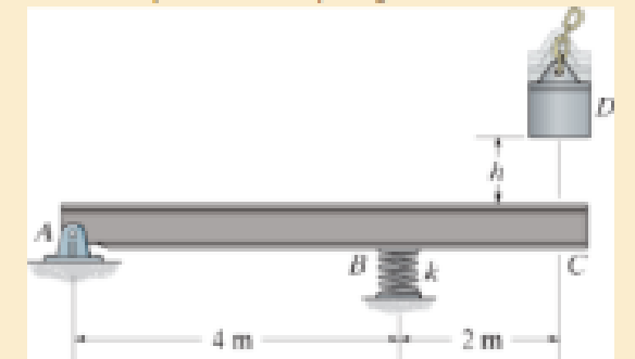
If the spring at B has a stiffness k = 200 kN/m. determine the maximum bending stress developed in the beam.
R14–2/3
Expert Solution & Answer
Want to see the full answer?
Check out a sample textbook solution
Students have asked these similar questions
(Read image) (Answer given)
Problem (17): water flowing in an open channel of a rectangular cross-section with width (b) transitions from a
mild slope to a steep slope (i.e., from subcritical to supercritical flow) with normal water depths of (y₁) and
(y2), respectively.
Given the values of y₁ [m], y₂ [m], and b [m], calculate the discharge in the channel (Q) in [Lit/s].
Givens:
y1 = 4.112 m
y2 =
0.387 m
b = 0.942 m
Answers:
( 1 ) 1880.186 lit/s
( 2 ) 4042.945 lit/s
( 3 ) 2553.11 lit/s
( 4 ) 3130.448 lit/s
Problem (14): A pump is being used to lift water from an underground
tank through a pipe of diameter (d) at discharge (Q). The total head
loss until the pump entrance can be calculated as (h₁ = K[V²/2g]), h
where (V) is the flow velocity in the pipe. The elevation difference
between the pump and tank surface is (h).
Given the values of h [cm], d [cm], and K [-], calculate the maximum
discharge Q [Lit/s] beyond which cavitation would take place at the
pump entrance. Assume Turbulent flow conditions.
Givens:
h = 120.31 cm
d = 14.455 cm
K = 8.976
Q
Answers:
(1) 94.917 lit/s
(2) 49.048 lit/s
( 3 ) 80.722 lit/s
68.588 lit/s
4
Chapter 14 Solutions
Mechanics of Materials
Ch. 14.2 - A material is subjected to a general state of...Ch. 14.2 - The strain-energy density for plane stress must be...Ch. 14.2 - The A-36 steel bar consists of two segments, one...Ch. 14.2 - If P = 10 kip, determine the total strain energy...Ch. 14.2 - Determine the maximum force P and the...Ch. 14.2 - Consider the thin-walled tube of Fig.5-26 . Use...Ch. 14.2 - Determine the bending strain energy in the 2-in...Ch. 14.2 - Determine the bending strain energy in the...Ch. 14.2 - Determine the bending strain energy in the simply...Ch. 14.3 - Determine the horizontal displacement of joint A....
Ch. 14.3 - Determine the vertical displacement of point S on...Ch. 14.3 - Prob. 40PCh. 14.3 - Determine the vertical displacement of end B of...Ch. 14.4 - A bar is 4 m long and has a diameter of 30 mm....Ch. 14.4 - Determine the diameter of a red brass C83400 bar...Ch. 14.4 - Prob. 44PCh. 14.4 - The collar has a weight of 50 lb and falls down...Ch. 14.4 - Prob. 52PCh. 14.4 - The composite aluminum 2014T6 bar is made from two...Ch. 14.4 - The composite aluminum 2014-T6 bar is made from...Ch. 14.4 - If the beam is a W1015, determine the maximum...Ch. 14.4 - If the maximum allowable bending stress for the...Ch. 14.4 - A 40-lb weight is dropped from a height of h = 2...Ch. 14.4 - The car bumper is made of...Ch. 14.6 - Determine the vertical displacement of joint A....Ch. 14.6 - Determine the vertical displacement of joint E....Ch. 14.6 - Determine the horizontal displacement of joint B...Ch. 14.6 - Determine the vertical displacement of joint C of...Ch. 14.7 - Determine the displacement at point C. El is...Ch. 14.7 - The beam is made of southern pine for which Ep =...Ch. 14.7 - Determine the displacement at point C. El is...Ch. 14.7 - Determine the slope at point C. El is constant....Ch. 14.7 - Determine the slope at point A. El is constant....Ch. 14.7 - Determine the displacement of point C of the beam...Ch. 14.7 - Determine the slope at B of the beam made from...Ch. 14.7 - The beam is made of Douglas fir. Determine the...Ch. 14.7 - Determine the displacement at pulley B. The A992...Ch. 14.7 - Determine the displacement at point C of the...Ch. 14.7 - Determine the slope at A of the shaft. El is...Ch. 14.7 - Determine the slope at A of the 2014T6 aluminum...Ch. 14.7 - Prob. 104PCh. 14.7 - Prob. 105PCh. 14.7 - Determine the displacement at point C of the W14 ...Ch. 14.7 - Determine the slope at A of the W14 26 beam made...Ch. 14.7 - Determine the slope at C of the overhang white...Ch. 14.7 - Determine the displacement at point D of the...Ch. 14.7 - Determine the maximum deflection of the beam...Ch. 14.7 - The beam is made of oak, for which Eo = 11 GPa....Ch. 14.7 - Determine the slope of the shaft at the bearing...Ch. 14.7 - The L-shaped frame is made from two segments, each...Ch. 14.7 - Determine the vertical displacement of the ring at...Ch. 14.7 - Determine the horizontal displacement at the...Ch. 14.9 - Solve Prob. 1473 using Castiglianos theorem. 1473....Ch. 14.9 - Solve Prob. 1474 using Castiglianos theorem. 1474....Ch. 14.9 - Prob. 125PCh. 14.9 - Prob. 126PCh. 14.9 - Prob. 127PCh. 14.9 - Solve Prob. 1478 using Castiglianos theorem. 1478....Ch. 14.9 - Solve Prob. 1481 using Castiglianos theorem. 1481....Ch. 14.9 - Solve Prob. 1482 using Castiglianos theorem. 1482....Ch. 14.9 - Solve Prob. 1485 using Castiglianos theorem. 1485....Ch. 14.9 - Solve Prob. 1486 using Castiglianos theorem. 1486....Ch. 14.10 - Solve Prob. 1490 using Castiglianos theorem. 1490....Ch. 14.10 - Solve Prob. 1491 using Castiglianos theorem. 1491....Ch. 14.10 - Prob. 135PCh. 14.10 - Solve Prob. 1493 using Castiglianos theorem. 1493....Ch. 14.10 - Solve Prob. 1495 using Castiglianos theorem. 1495....Ch. 14.10 - Solve Prob. 1496 using Castiglianos theorem. 1496....Ch. 14.10 - Prob. 139PCh. 14.10 - Prob. 140PCh. 14.10 - Prob. 141PCh. 14 - A = 2300 mm2, I = 9.5(106) mm4. R141Ch. 14 - If the spring at B has a stiffness k = 200 kN/m....Ch. 14 - The spring at B has a stiffness k = 200 kN/m....Ch. 14 - If they each have a diameter of 30 mm, determine...Ch. 14 - and a length of 10 in. It is struck by a hammer...Ch. 14 - Determine the total axial and bending strain...Ch. 14 - The truss is made from A992 steel rods each having...Ch. 14 - The truss is made from A992 steel rods each having...Ch. 14 - El is constant. Use the method of virtual work....Ch. 14 - using Castiglianos theorem. R149. The cantilevered...
Additional Engineering Textbook Solutions
Find more solutions based on key concepts
The ____________ is always transparent.
Web Development and Design Foundations with HTML5 (8th Edition)
The job of the _____ is to fetch instructions, carry out the operations commanded by the instructions, and prod...
Starting Out With Visual Basic (8th Edition)
Porter’s competitive forces model: The model is used to provide a general view about the firms, the competitors...
Management Information Systems: Managing The Digital Firm (16th Edition)
This optional Google account security feature sends you a message with a code that you must enter, in addition ...
SURVEY OF OPERATING SYSTEMS
CONCEPT QUESTIONS
15.CQ3 The ball rolls without slipping on the fixed surface as shown. What is the direction ...
Vector Mechanics for Engineers: Statics and Dynamics
What types of coolant are used in vehicles?
Automotive Technology: Principles, Diagnosis, And Service (6th Edition) (halderman Automotive Series)
Knowledge Booster


Learn more about
Need a deep-dive on the concept behind this application? Look no further. Learn more about this topic, mechanical-engineering and related others by exploring similar questions and additional content below.Similar questions
- Problem (13): A pump is being used to lift water from the bottom tank to the top tank in a galvanized iron pipe at a discharge (Q). The length and diameter of the pipe section from the bottom tank to the pump are (L₁) and (d₁), respectively. The length and diameter of the pipe section from the pump to the top tank are (L2) and (d2), respectively. Given the values of Q [L/s], L₁ [m], d₁ [m], L₂ [m], d₂ [m], calculate total head loss due to friction (i.e., major loss) in the pipe (hmajor-loss) in [cm]. Givens: L₁,d₁ Pump L₂,d2 오 0.533 lit/s L1 = 6920.729 m d1 = 1.065 m L2 = 70.946 m d2 0.072 m Answers: (1) 3.069 cm (2) 3.914 cm ( 3 ) 2.519 cm ( 4 ) 1.855 cm TABLE 8.1 Equivalent Roughness for New Pipes Pipe Riveted steel Concrete Wood stave Cast iron Galvanized iron Equivalent Roughness, & Feet Millimeters 0.003-0.03 0.9-9.0 0.001-0.01 0.3-3.0 0.0006-0.003 0.18-0.9 0.00085 0.26 0.0005 0.15 0.045 0.000005 0.0015 0.0 (smooth) 0.0 (smooth) Commercial steel or wrought iron 0.00015 Drawn…arrow_forwardThe flow rate is 12.275 Liters/s and the diameter is 6.266 cm.arrow_forwardAn experimental setup is being built to study the flow in a large water main (i.e., a large pipe). The water main is expected to convey a discharge (Qp). The experimental tube will be built at a length scale of 1/20 of the actual water main. After building the experimental setup, the pressure drop per unit length in the model tube (APm/Lm) is measured. Problem (20): Given the value of APm/Lm [kPa/m], and assuming pressure coefficient similitude, calculate the drop in the pressure per unit length of the water main (APP/Lp) in [Pa/m]. Givens: AP M/L m = 590.637 kPa/m meen Answers: ( 1 ) 59.369 Pa/m ( 2 ) 73.83 Pa/m (3) 95.443 Pa/m ( 4 ) 44.444 Pa/m *******arrow_forward
- Find the reaction force in y if Ain = 0.169 m^2, Aout = 0.143 m^2, p_in = 0.552 atm, Q = 0.367 m^3/s, α = 31.72 degrees. The pipe is flat on the ground so do not factor in weight of the pipe and fluid.arrow_forwardFind the reaction force in x if Ain = 0.301 m^2, Aout = 0.177 m^2, p_in = 1.338 atm, Q = 0.669 m^3/s, and α = 37.183 degreesarrow_forwardProblem 5: Three-Force Equilibrium A structural connection at point O is in equilibrium under the action of three forces. • • . Member A applies a force of 9 kN vertically upward along the y-axis. Member B applies an unknown force F at the angle shown. Member C applies an unknown force T along its length at an angle shown. Determine the magnitudes of forces F and T required for equilibrium, assuming 0 = 90° y 9 kN Aarrow_forward
- Problem 19: Determine the force in members HG, HE, and DE of the truss, and state if the members are in tension or compression. 4 ft K J I H G B C D E F -3 ft -3 ft 3 ft 3 ft 3 ft- 1500 lb 1500 lb 1500 lb 1500 lb 1500 lbarrow_forwardProblem 14: Determine the reactions at the pin A, and the tension in cord. Neglect the thickness of the beam. F1=26kN F2 13 12 80° -2m 3marrow_forwardProblem 22: Determine the force in members GF, FC, and CD of the bridge truss and state if the members are in tension or compression. F 15 ft B D -40 ft 40 ft -40 ft 40 ft- 5 k 10 k 15 k 30 ft Earrow_forward
- Problem 20: Determine the force in members BC, HC, and HG. After the truss is sectioned use a single equation of equilibrium for the calculation of each force. State if the members are in tension or compression. 5 kN 4 kN 4 kN 3 kN 2 kN B D E F 3 m -5 m- -5 m- 5 m 5 m-arrow_forwardAn experimental setup is being built to study the flow in a large water main (i.e., a large pipe). The water main is expected to convey a discharge (Qp). The experimental tube will be built at a length scale of 1/20 of the actual water main. After building the experimental setup, the pressure drop per unit length in the model tube (APm/Lm) is measured. Problem (19): Given the value of Qp [m³/s], and assuming Reynolds number similitude between the water main and experimental tube, calculate the flow rate in the model tube (Qm) in [lit/s]. = 30.015 m^3/sarrow_forwardProblem 11: The lamp has a weight of 15 lb and is supported by the six cords connected together as shown. Determine the tension in each cord and the angle 0 for equilibrium. Cord BC is horizontal. E 30° B 60° Aarrow_forward
arrow_back_ios
SEE MORE QUESTIONS
arrow_forward_ios
Recommended textbooks for you
 Elements Of ElectromagneticsMechanical EngineeringISBN:9780190698614Author:Sadiku, Matthew N. O.Publisher:Oxford University Press
 Mechanics of Materials (10th Edition)Mechanical EngineeringISBN:9780134319650Author:Russell C. HibbelerPublisher:PEARSON
 Thermodynamics: An Engineering ApproachMechanical EngineeringISBN:9781259822674Author:Yunus A. Cengel Dr., Michael A. BolesPublisher:McGraw-Hill Education
 Control Systems EngineeringMechanical EngineeringISBN:9781118170519Author:Norman S. NisePublisher:WILEY
 Mechanics of Materials (MindTap Course List)Mechanical EngineeringISBN:9781337093347Author:Barry J. Goodno, James M. GerePublisher:Cengage Learning
 Engineering Mechanics: StaticsMechanical EngineeringISBN:9781118807330Author:James L. Meriam, L. G. Kraige, J. N. BoltonPublisher:WILEY
Elements Of Electromagnetics
Mechanical Engineering
ISBN:9780190698614
Author:Sadiku, Matthew N. O.
Publisher:Oxford University Press
Mechanics of Materials (10th Edition)
Mechanical Engineering
ISBN:9780134319650
Author:Russell C. Hibbeler
Publisher:PEARSON
Thermodynamics: An Engineering Approach
Mechanical Engineering
ISBN:9781259822674
Author:Yunus A. Cengel Dr., Michael A. Boles
Publisher:McGraw-Hill Education
Control Systems Engineering
Mechanical Engineering
ISBN:9781118170519
Author:Norman S. Nise
Publisher:WILEY
Mechanics of Materials (MindTap Course List)
Mechanical Engineering
ISBN:9781337093347
Author:Barry J. Goodno, James M. Gere
Publisher:Cengage Learning
Engineering Mechanics: Statics
Mechanical Engineering
ISBN:9781118807330
Author:James L. Meriam, L. G. Kraige, J. N. Bolton
Publisher:WILEY
Everything About COMBINED LOADING in 10 Minutes! Mechanics of Materials; Author: Less Boring Lectures;https://www.youtube.com/watch?v=N-PlI900hSg;License: Standard youtube license