
Concept explainers
Videos
(a)
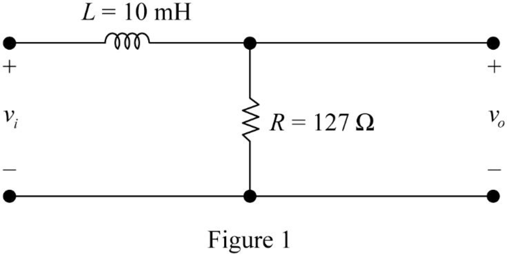
Find the value of the cutoff frequency in hertz for the RL filter shown in given figure.
(a)
Answer to Problem 1P
The value of the cutoff frequency
Explanation of Solution
Given data:
Refer to given figure in the textbook.
Formula used:
Write the expression to calculate the angular cutoff frequency.
Here,
Write the expression to calculate the cutoff frequency of the RL low-pass filter.
Here,
Calculation:
The given filter circuit is drawn as Figure 1.
Substitute
Simplify the above equation to find
Substitute
Rearrange the above equation to find
Conclusion:
Thus, the value of the cutoff frequency
(b)
Find the value of the transfer function
(b)
Answer to Problem 1P
The value of the transfer function
Explanation of Solution
Formula used:
Write the expression to calculate the impedance of the passive elements resistor and inductor.
Calculation:
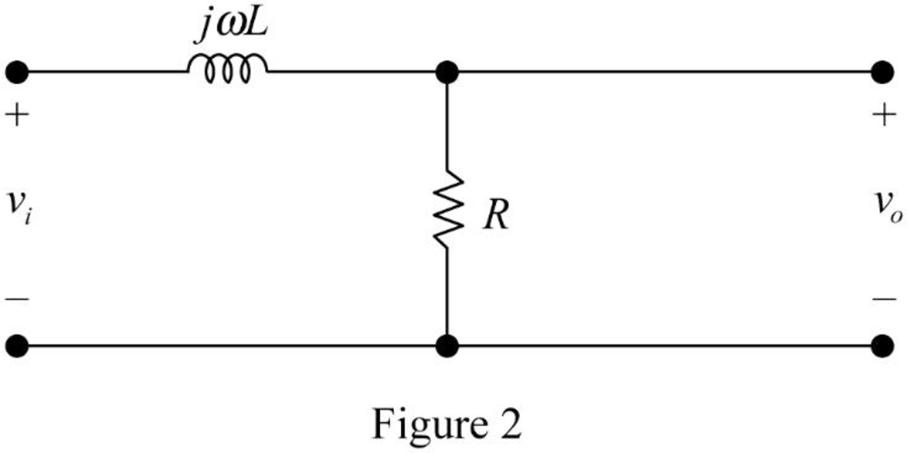
The impedance circuit of the Figure 1 is drawn as Figure 2 using the equations (3) and (4).
Apply voltage division rule on Figure 2 to find
Rearrange the above equation to find
Substitute the equation (2) in above equation to find
Write the expression to calculate the transfer function of the circuit in Figure 2.
Substitute
Substitute
Substitute
Substitute
Substitute
Substitute
Substitute
Substitute
Conclusion:
Thus, the value of the transfer function
(c)
Find the steady state expression for the output voltage
(c)
Answer to Problem 1P
The steady state expression for the output voltage
Explanation of Solution
Given data:
The input voltage is,
Calculation:
From part (b),
Rearrange the above equation to find
Substitute
Substitute
Substitute
Simplify the above equation to find
Substitute
Substitute
Simplify the above equation to find
Substitute
Substitute
Simplify the above equation to find
Conclusion:
Thus, the steady state expression for the output voltage
Want to see more full solutions like this?
Chapter 14 Solutions
Electric Circuits. (11th Edition)


- i need help with this question i tried by myself and so i am uploadding the question to be quided with step by step solution and please do not use chat gpt i am trying to learn thank you. i only need help with the second question pleasearrow_forwardPlease provide explaination and workings.arrow_forwardDon't use ai to answer I will report you answer..arrow_forward
- Don't use ai to answer I will report you answerarrow_forward3) Find the valve of V using the Thevenin Equivalent Circuit and then determine if the 8 ohm resistor allows maximum power transfer. If not, then what value should the 8 ohm resist or be changed to for maximum power transfer? ZA 360 Am 6t + 22V V 3402 22 62 Mw marrow_forwardFind the valve of the voltage Vx using the THEVENIN 2) equivalent circuit and redo the problem with the NORTON equivalent circuit. Show both the flavinen and Norton Circuits DAY ww 1 23 www + 4444 5 63arrow_forward
 Introductory Circuit Analysis (13th Edition)Electrical EngineeringISBN:9780133923605Author:Robert L. BoylestadPublisher:PEARSON
 Delmar's Standard Textbook Of ElectricityElectrical EngineeringISBN:9781337900348Author:Stephen L. HermanPublisher:Cengage Learning
 Programmable Logic ControllersElectrical EngineeringISBN:9780073373843Author:Frank D. PetruzellaPublisher:McGraw-Hill Education
 Fundamentals of Electric CircuitsElectrical EngineeringISBN:9780078028229Author:Charles K Alexander, Matthew SadikuPublisher:McGraw-Hill Education
 Electric Circuits. (11th Edition)Electrical EngineeringISBN:9780134746968Author:James W. Nilsson, Susan RiedelPublisher:PEARSON
 Engineering ElectromagneticsElectrical EngineeringISBN:9780078028151Author:Hayt, William H. (william Hart), Jr, BUCK, John A.Publisher:Mcgraw-hill Education,