
Concept explainers
Videos
A = 2300 mm2, I = 9.5(106) mm4.
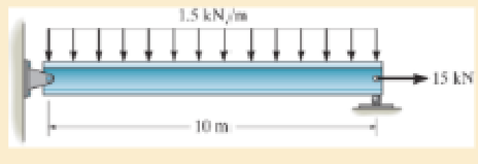
R14–1
Answer to Problem 14.1RP
The total axial and bending strain energy in the A992 steel beam is
Explanation of Solution
Given information:
The cross-sectional area of the beam is
Moment of inertia of the beam is
Assumption:
The modulus of elasticity or Young’s modulus of theA992 steelis
Explanation:
Determine the reactions:
Entire beam:
Show the free body diagram of the entire beam as in Figure 1.
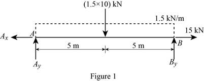
Moment about the point A:
Determine the vertical reaction at point B by taking moment about point A.
Along the vertical direction:
Determine the vertical reaction at point B by resolving the vertical component of forces.
Along the horizontal direction:
Determine the horizontal reaction at point A by resolving the horizontal component of force.
Show the calculation of reaction as follows:
Solve Equation (1).
Substitute 7.5kN for
Solve Equation (3).
Region
Show the free-body diagram of the section as in Figure 2.
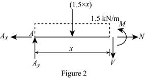
Moment about the section:
Determine the moment at section by taking moment about the section.
Along the horizontal direction:
Determine the normal axial force at the section by resolving the horizontal component of forces.
Show the calculation of values as follows:
Substitute 7.5kN for
Substitute 15 kN for
Strain energy due to axial load:
Determine the strain energy of a bar of constant cross-sectional area A and constant internal axial load N using the equation.
Here, N is the axial load, L is the length of beam, E is Young’s modulus or modulus of elasticity, and A is cross-sectional area of the beam.
Substitute 15 kN for N, 10 m for L,
Strain energy due to Bending:
Determine the strain energy in the beam due to bending using the equation.
Here, M is the moment in the beam and I is the moment of inertia of the beam.
Substitute 10 m for L,
Total strain energy:
Determine the total strain energy by adding the strain energy due to axial load and the strain energy due to bending.
Substitute 2.4456 J for
Thus, the total axial and bending strain energy in the A992 steel beam is
Want to see more full solutions like this?
Chapter 14 Solutions
Mechanics of Materials (Custom)
Additional Engineering Textbook Solutions
Management Information Systems: Managing The Digital Firm (16th Edition)
Database Concepts (8th Edition)
BASIC BIOMECHANICS
Java: An Introduction to Problem Solving and Programming (8th Edition)
Elementary Surveying: An Introduction To Geomatics (15th Edition)
Electric Circuits. (11th Edition)


- PROBLEM 3.46 The solid cylindrical rod BC of length L = 600 mm is attached to the rigid lever AB of length a = 380 mm and to the support at C. When a 500 N force P is applied at A, design specifications require that the displacement of A not exceed 25 mm when a 500 N force P is applied at A For the material indicated determine the required diameter of the rod. Aluminium: Tall = 65 MPa, G = 27 GPa. Aarrow_forwardFind the equivalent mass of the rocker arm assembly with respect to the x coordinate. k₁ mi m2 k₁arrow_forward2. Figure below shows a U-tube manometer open at both ends and containing a column of liquid mercury of length l and specific weight y. Considering a small displacement x of the manometer meniscus from its equilibrium position (or datum), determine the equivalent spring constant associated with the restoring force. Datum Area, Aarrow_forward
- 1. The consequences of a head-on collision of two automobiles can be studied by considering the impact of the automobile on a barrier, as shown in figure below. Construct a mathematical model (i.e., draw the diagram) by considering the masses of the automobile body, engine, transmission, and suspension and the elasticity of the bumpers, radiator, sheet metal body, driveline, and engine mounts.arrow_forward3.) 15.40 – Collar B moves up at constant velocity vB = 1.5 m/s. Rod AB has length = 1.2 m. The incline is at angle = 25°. Compute an expression for the angular velocity of rod AB, ė and the velocity of end A of the rod (✓✓) as a function of v₂,1,0,0. Then compute numerical answers for ȧ & y_ with 0 = 50°.arrow_forward2.) 15.12 The assembly shown consists of the straight rod ABC which passes through and is welded to the grectangular plate DEFH. The assembly rotates about the axis AC with a constant angular velocity of 9 rad/s. Knowing that the motion when viewed from C is counterclockwise, determine the velocity and acceleration of corner F.arrow_forward
- 500 Q3: The attachment shown in Fig.3 is made of 1040 HR. The static force is 30 kN. Specify the weldment (give the pattern, electrode number, type of weld, length of weld, and leg size). Fig. 3 All dimension in mm 30 kN 100 (10 Marks)arrow_forward(read image) (answer given)arrow_forwardA cylinder and a disk are used as pulleys, as shown in the figure. Using the data given in the figure, if a body of mass m = 3 kg is released from rest after falling a height h 1.5 m, find: a) The velocity of the body. b) The angular velocity of the disk. c) The number of revolutions the cylinder has made. T₁ F Rd = 0.2 m md = 2 kg T T₂1 Rc = 0.4 m mc = 5 kg ☐ m = 3 kgarrow_forward
- (read image) (answer given)arrow_forward11-5. Compute all the dimensional changes for the steel bar when subjected to the loads shown. The proportional limit of the steel is 230 MPa. 265 kN 100 mm 600 kN 25 mm thickness X Z 600 kN 450 mm E=207×103 MPa; μ= 0.25 265 kNarrow_forwardT₁ F Rd = 0.2 m md = 2 kg T₂ Tz1 Rc = 0.4 m mc = 5 kg m = 3 kgarrow_forward
 Elements Of ElectromagneticsMechanical EngineeringISBN:9780190698614Author:Sadiku, Matthew N. O.Publisher:Oxford University Press
 Mechanics of Materials (10th Edition)Mechanical EngineeringISBN:9780134319650Author:Russell C. HibbelerPublisher:PEARSON
 Thermodynamics: An Engineering ApproachMechanical EngineeringISBN:9781259822674Author:Yunus A. Cengel Dr., Michael A. BolesPublisher:McGraw-Hill Education
 Control Systems EngineeringMechanical EngineeringISBN:9781118170519Author:Norman S. NisePublisher:WILEY
 Mechanics of Materials (MindTap Course List)Mechanical EngineeringISBN:9781337093347Author:Barry J. Goodno, James M. GerePublisher:Cengage Learning
 Engineering Mechanics: StaticsMechanical EngineeringISBN:9781118807330Author:James L. Meriam, L. G. Kraige, J. N. BoltonPublisher:WILEY