The structure stiffness matrix for the truss.
Answer to Problem 14.1P
The structure stiffness matrix for the truss is shown below.
Explanation of Solution
Concept Used:
Write the expression for direction cosine in x-direction.
Here, coordinate of
Write the expression for direction cosine in x-direction.
Here, coordinate of
Write the stiffness matrix for the member.
Here, cross-sectional area of the member is
Write the expression for total structural stiffness matrix.
Here, the structural stiffness matrix is
Calculation:
The free body diagram of the truss is shown below.
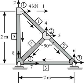
Figure (1)
Consider the member-1.
Calculate the length of member
Calculate direction cosine in x-direction.
Substitute
Calculate direction cosine in y-direction.
Substitute
The stiffness matrix for member-1 is shown below.
Substitute
Consider the member-
Calculate the length of member
Calculate direction cosine in x-direction.
Substitute
Calculate direction cosine in y-direction.
Substitute
The stiffness matrix for member-2 is shown below.
Substitute
Consider the member-
Calculate direction cosine in x-direction.
Substitute
Calculate direction cosine in y-direction.
Substitute
The stiffness matrix for member-3 is shown below.
Substitute
Consider the member-
Calculate the length of member
Calculate direction cosine in x-direction.
Substitute
Calculate direction cosine in y-direction.
Substitute
The stiffness matrix for member-4 is shown below.
Substitute
Consider the member-
Calculate direction cosine in x-direction.
Substitute
Calculate direction cosine in y-direction.
Substitute
The stiffness matrix for member-5 is shown below.
Substitute
Calculate total structural stiffness matrix.
Substitute the values of
Conclusion:
The structure stiffness matrix for the truss is shown below.
Want to see more full solutions like this?
Chapter 14 Solutions
Structural Analysis, Student Value Edition

- A tension member made of L4x4x1/2 is connected to gusset plate with welds. Using E70electrode and ½ inch weld size, design the balanced weld lengths.( Use AISC manual, LRFD units)(Previous solution was incorrect)arrow_forwardQ1: determine the area of steel for the slab that rests on brick walls and is shown in the figure. Use the following data: f'c = 25 MPa, fy = 420 MPa, L.L. = 1.5 kN/m², D.L. = 3 kN/m² (without self-weight). Rate from (1 to 4) your ability to solve the problem 7 m 0.3 m 0.3 marrow_forwardA rigging job calls for lifting a structure that weighs 150 tons. Two cranes are available, one with a rated capacity of 85 tons and the other with a rated capacity of 120 tons. The total weight of the rigging required to make the lift is 15 tons, of which 10 tons is to be carried by the larger craneand 5 tons is to be carried by the smaller crane. If the cranes are to be loaded in proportion to their net capacities, what should be the approximate net load on the 120-ton crane?arrow_forward
- I need detailed help solving this exercise from homework of Engineering Mathematics II.I do not really understand how to do, please do it step by step, not that long but clear. Thank you!P.S.: Please do not use AI, thanks!arrow_forwardI need detailed help solving this exercise from homework of Engineering Mathematics II.I do not really understand how to do, please do it step by step, not that long but clear. Thank you!P.S.: Please do not use AI, thanks!arrow_forwarda) For the truss shown in Fig 2, determine the stiffness matrices of elements 2, 3 and 4 in the in the global co-ordinate system. Assume for each member A = 0.0015 m2 and E = 200 GPa. Indicate the degrees-of freedom in all the stiffness matrices. b) Determine the stiffness matrix of the whole truss in the global co-ordinate system. Clearly indicate the degrees-of freedom numbers in the stiffness matrix. c) Calculate all the nodal displacements and all the member forces of the truss.arrow_forward
- I want an answer very quickly, pleasearrow_forwardI want an answer very quickly, pleasearrow_forwardQ1/ Choose the correct answer for the following: 1- Cantilever retaining walls is suitable for retaining backfill about a- 8m d-4m b- 12m c- 2m e- Any height 2-The shear key is provided to a- Avoid friction behind the wall d- All of the above b- Improve appearance e- None of the above c- Increase passive resistance types of retaining wall may b- Semi-gravity retaining walls d-Counterfort retaining walls be classified as follows: 3- The common a- Gravity retaining walls walls c- Cantilever retaining e- All the mentioned 4-Related to Stability of RW, Which of the following does not represent a potential failure mode for a retaining wall? a-Bearing capacity failure of the foundation soil. b- Wall cracking due to thermal expansion. c- Excessive settlement due to weak soil layer. d- Shear failure within the foundation soil adjacent to the wall. e-Sliding along the base due to insufficient friction. 5- If the desired factor of safety against sliding is not met, which strategy is NOT a…arrow_forward

 Structural Analysis (10th Edition)Civil EngineeringISBN:9780134610672Author:Russell C. HibbelerPublisher:PEARSON
 Principles of Foundation Engineering (MindTap Cou...Civil EngineeringISBN:9781337705028Author:Braja M. Das, Nagaratnam SivakuganPublisher:Cengage Learning
 Fundamentals of Structural AnalysisCivil EngineeringISBN:9780073398006Author:Kenneth M. Leet Emeritus, Chia-Ming Uang, Joel LanningPublisher:McGraw-Hill Education
 Traffic and Highway EngineeringCivil EngineeringISBN:9781305156241Author:Garber, Nicholas J.Publisher:Cengage Learning