
Loose Leaf for Engineering Circuit Analysis Format: Loose-leaf
9th Edition
ISBN: 9781259989452
Author: Hayt
Publisher: Mcgraw Hill Publishers
expand_more
expand_more
format_list_bulleted
Concept explainers
Videos
Textbook Question
Chapter 13.1, Problem 1P
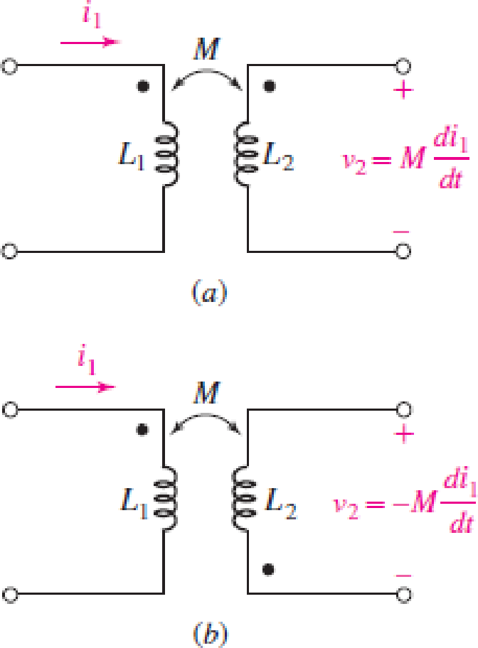
Assuming M = 10 H, coil L2 is open-circuited, and i1 = −2e−5t A, find the voltage v2 for (a) Fig. 13.2a; (b) Fig. 13.2b.
FIGURE 13.2
Expert Solution & Answer
Want to see the full answer?
Check out a sample textbook solution
Students have asked these similar questions
A single tone is modulated using FM transmitter. The SNR, at the input of the demodulator
20 dB. If the maximum frequency of the modulating signal is 4 kHz, and the maximum
equency deviation is 12 kHz, find the SNR, and the bandwidth (using Carson rule) at the
ollowing conditions:
. For the given values of fm and Af.
!. If the amplitude of the modulating signal is increased by 80%.
3. If the amplitude of the modulating signal is decreased by 50%, and frequency of modulating
signal is increased by 50%.
The circuit shown below on the left has the following parameters:
V₁ = 5 V.
R₁ = 40,
R₂ = 40,
α = 0.1.
This circuit can be replaced by an equivalent circuit shown below on the right such that the voltage and current received by an arbitrary load resistor RL, are identical
when connected to either circuits.
Determine the value of the resistor R (in ) in the equivalent circuit.
R₁
Rx
R2
R₁
Vx
R₁
Vi
απ.
b
1. Consider the following a unity feedback control system.
R(s) +
E(s)
500(s+2)(s+5)(s+6)
s(s+8)(s+10)(s+12)
-Y(s)
Find the followings:
a) Type of the system
b) Static position error constant Kp, Static velocity error constant Ry and Static
acceleration error constant Ka
c) Find the steady-state error of the system for (i) step input 1(t), (ii) ramp input t 1(t),
(iii) parabolic input t² 1(t).
2. Repeat the above problem for the following system.
R(s) + E(s)
500(s + 2)(s + 5)
(s+8)(s+ 10)(s+12)
Y(s)
3. Repeat the above problem for the following system.
R(s) +
E(s) 500(s+2)(s+4)(s+5)(s+6)(s+7)
s²(s+8)(s+10)(s+12)
Y(s)
Chapter 13 Solutions
Loose Leaf for Engineering Circuit Analysis Format: Loose-leaf
Ch. 13.1 - Assuming M = 10 H, coil L2 is open-circuited, and...Ch. 13.1 - For the circuit of Fig. 13.9, write appropriate...Ch. 13.1 - For the circuit of Fig. 13.11, write an...Ch. 13.2 - Let is = 2 cos 10t A in the circuit of Fig. 13.14,...Ch. 13.3 - Element values for a certain linear transformer...Ch. 13.3 - (a) If the two networks shown in Fig. 13.20 are...Ch. 13.3 - If the networks in Fig. 13.23 are equivalent,...Ch. 13.4 - Prob. 8PCh. 13.4 - Let N1 = 1000 turns and N2 = 5000 turns in the...Ch. 13 - Prob. 1E
Ch. 13 - With respect to Fig. 13.36, assume L1 = 500 mH, L2...Ch. 13 - The circuit in Fig. 13.36 has a sinusoidal input...Ch. 13 - Prob. 4ECh. 13 - Prob. 5ECh. 13 - The circuit in Fig. 13.38 has a sinusoidal input...Ch. 13 - The physical construction of three pairs of...Ch. 13 - Prob. 8ECh. 13 - Prob. 9ECh. 13 - Calculate v1 and v2 if i1 = 5 sin 40t mA and i2 =...Ch. 13 - Prob. 11ECh. 13 - For the circuit of Fig. 13.41, calculate I1, I2,...Ch. 13 - Prob. 13ECh. 13 - Prob. 14ECh. 13 - In the circuit of Fig. 13.43, M is reduced by an...Ch. 13 - Prob. 16ECh. 13 - Prob. 17ECh. 13 - Prob. 18ECh. 13 - Prob. 19ECh. 13 - Note that there is no mutual coupling between the...Ch. 13 - Prob. 21ECh. 13 - (a) Find Zin(j) for the network of Fig 13.50. (b)...Ch. 13 - For the coupled coils of Fig. 13.51, L1 = L2 = 10...Ch. 13 - Prob. 24ECh. 13 - Prob. 25ECh. 13 - Prob. 26ECh. 13 - Consider the circuit represented in Fig. 13.53....Ch. 13 - Compute v1, v2, and the average power delivered to...Ch. 13 - Assume the following values for the circuit...Ch. 13 - Prob. 30ECh. 13 - Prob. 31ECh. 13 - Prob. 32ECh. 13 - Prob. 33ECh. 13 - Prob. 34ECh. 13 - Prob. 35ECh. 13 - Prob. 36ECh. 13 - Prob. 37ECh. 13 - FIGURE 13.60 For the circuit of Fig. 13.60, redraw...Ch. 13 - Prob. 39ECh. 13 - Prob. 40ECh. 13 - Calculate the average power delivered to the 400 m...Ch. 13 - Prob. 42ECh. 13 - Calculate the average power delivered to each...Ch. 13 - Prob. 44ECh. 13 - Prob. 45ECh. 13 - Prob. 46ECh. 13 - Prob. 47ECh. 13 - Prob. 48ECh. 13 - A transformer whose nameplate reads 2300/230 V, 25...Ch. 13 - Prob. 52ECh. 13 - As the lead singer in the local rock band, you...Ch. 13 - Obtain an expression for V2/Vs in the circuit of...Ch. 13 - Prob. 55E
Additional Engineering Textbook Solutions
Find more solutions based on key concepts
Assume a telephone signal travels through a cable at two-thirds the speed of light. How long does it take the s...
Electric Circuits. (11th Edition)
What is an uninitialized variable?
Starting Out with Programming Logic and Design (5th Edition) (What's New in Computer Science)
A nozzle at A discharges water with an initial velocity of 36 ft/s at an angle with the horizontal. Determine ...
Vector Mechanics For Engineers
This optional Google account security feature sends you a message with a code that you must enter, in addition ...
SURVEY OF OPERATING SYSTEMS
Locate the centroid of the area. Prob. 9-17
INTERNATIONAL EDITION---Engineering Mechanics: Statics, 14th edition (SI unit)
A byte is made up of eight a. CPUs b. addresses c. variables d. bits
Starting Out with Java: From Control Structures through Objects (7th Edition) (What's New in Computer Science)
Knowledge Booster


Learn more about
Need a deep-dive on the concept behind this application? Look no further. Learn more about this topic, electrical-engineering and related others by exploring similar questions and additional content below.Similar questions
- 4. Consider a unity (negative) feedback control system whose open-loop transfer function is given by the following. 2 G(s) = s³ (s + 2) Find the steady-state error of the system for each of the following inputs. = a) u(t) (t²+8t+5) 1(t) b) u(t) = 3t³ 1(t) c) u(t) (t+5t² - 1) 1(t) =arrow_forward1 2. For the following closed-loop system, G(s) = and H(s) = ½ (s+4)(s+6) a. Please draw the root locus by hand and mark the root locus with arrows. Calculate the origin and angle for asymptotes. b. Use Matlab to draw the root locus to verify your sketch. Input R(s) Output C(s) KG(s) H(s)arrow_forward5. Consider following feedback system. R(s) + 100 S+4 +1 Find the steady-state error for (i) step input and (ii) ramp input.arrow_forward
- 6. Find (i) settling time (Ts), (ii) rise time (Tr), (iii) peak time (Tp), and (iv) percent overshoot (% OS) for each of the following systems whose transfer functions are given by: a) H(s) = 5 s²+12s+20 5 b) H(s) = s²+6s+25 c) H(s) = (s+2) (s²+12s+20) (s²+4s+13) Use dominant pole approximation if needed.arrow_forward7. Answer the following questions. Take help from ChatGPT to answer these questions (if you need). But write the answers briefly using your own words with no more than two sentences and make sure you check whether ChatGPT is giving you the appropriate answers in the context of class. a) Why do we need transient performance metrics? Name a few of such metrics. b) Define (i) settling time, (ii) rise time, (iii) peak time and (iv) percent overshoot. c) What is damping ratio? How does overshoot change with the change of damping ratio? When do we have zero overshoot? d) What is the criterion for selecting dominant pole in higher order systems? When dominant pole approximation is not valid? How will you calculate the transient performance metrics for the case when dominant pole approximation does not hold?arrow_forwardThe transformer rating is 1200:2400 V @ 120 kVA. What is the apparent power provided by the source? What does this mean for the operation of the transformer? Draw the power triangle at the source and calculate the power factor. The magnitude of the voltage source is given in VRMS.arrow_forward
- Don't use ai to answer i will report your answerarrow_forwarda) Find the Real and Imaginary Voltage across the inductor to 3 decimal points. b) Find the current and phase angle (phasor) magnitude from the Vs source to 3 decimal points. c) Find the magnitude and phase angle of the complex power(phasor) delivered by the Vs source to 3 decimal points.arrow_forwardConsider the circuit diagram below. If four identical capacitors, each with a capacitance of 0.07 F, are used to smooth the output, what will the ripple voltage VR be? The diode forward bias voltage, VF, is found to be 0.5 V. Note that the amplitude of v(t) is given in VRMS.arrow_forward
- a) Find the complex power absorbed by the -j3 ohm capacitor to 3 decimal points.b) Find the complex power absorbed by the 4 ohm resistor to 3 decimal pointsc) Find the complex power absorbed by the j5 ohm inductor to 3 decimal points.arrow_forwardI am looking for schematic ideas or recommendations for designing the required step-down system. Since the input is a 600V DC supply, a DC-DC converter may be necessary, as transformers are typically used for AC voltage. Key considerations would include: Voltage regulation: Ensuring a stable and consistent 120V DC output.Component selection: Choosing appropriate DC-DC converter modules, capacitors for filtering, and protective components such as fuses or circuit breakers.Lighting system: Recommendations on energy-efficient lighting options like LEDs, which work well with DC power and offer durability for railway applications.Thermal management: Addressing heat dissipation within the converter and lighting circuit.Safety and standards: Complying with safety regulations for electrical systems in railways. I would greatly appreciate detailed insights into the design process, including key circuit components and configurations, as well as any schematic diagrams or references.arrow_forward1 2. For the following closed-loop system, G(s) = and H(s) = ½ (s+4)(s+6) a. Please draw the root locus by hand and mark the root locus with arrows. Calculate the origin and angle for asymptotes. b. Use Matlab to draw the root locus to verify your sketch. Input R(s) Output C(s) KG(s) H(s)arrow_forward
arrow_back_ios
SEE MORE QUESTIONS
arrow_forward_ios
Recommended textbooks for you
 Introductory Circuit Analysis (13th Edition)Electrical EngineeringISBN:9780133923605Author:Robert L. BoylestadPublisher:PEARSON
 Delmar's Standard Textbook Of ElectricityElectrical EngineeringISBN:9781337900348Author:Stephen L. HermanPublisher:Cengage Learning
 Programmable Logic ControllersElectrical EngineeringISBN:9780073373843Author:Frank D. PetruzellaPublisher:McGraw-Hill Education
 Fundamentals of Electric CircuitsElectrical EngineeringISBN:9780078028229Author:Charles K Alexander, Matthew SadikuPublisher:McGraw-Hill Education
 Electric Circuits. (11th Edition)Electrical EngineeringISBN:9780134746968Author:James W. Nilsson, Susan RiedelPublisher:PEARSON
 Engineering ElectromagneticsElectrical EngineeringISBN:9780078028151Author:Hayt, William H. (william Hart), Jr, BUCK, John A.Publisher:Mcgraw-hill Education,
Introductory Circuit Analysis (13th Edition)
Electrical Engineering
ISBN:9780133923605
Author:Robert L. Boylestad
Publisher:PEARSON
Delmar's Standard Textbook Of Electricity
Electrical Engineering
ISBN:9781337900348
Author:Stephen L. Herman
Publisher:Cengage Learning
Programmable Logic Controllers
Electrical Engineering
ISBN:9780073373843
Author:Frank D. Petruzella
Publisher:McGraw-Hill Education
Fundamentals of Electric Circuits
Electrical Engineering
ISBN:9780078028229
Author:Charles K Alexander, Matthew Sadiku
Publisher:McGraw-Hill Education
Electric Circuits. (11th Edition)
Electrical Engineering
ISBN:9780134746968
Author:James W. Nilsson, Susan Riedel
Publisher:PEARSON
Engineering Electromagnetics
Electrical Engineering
ISBN:9780078028151
Author:Hayt, William H. (william Hart), Jr, BUCK, John A.
Publisher:Mcgraw-hill Education,
TRANSFORMERS - What They Are, How They Work, How Electricians Size Them; Author: Electrician U;https://www.youtube.com/watch?v=tXPy4OE7ApE;License: Standard Youtube License