
Concept explainers
Calculate the support reactions for the given beam using method of consistent deformation.
Sketch the shear and bending moment diagrams for the given beam.
Answer to Problem 54P
The horizontal reaction at A is
The vertical reaction at A is
The vertical reaction at C is
The vertical reaction at E is
The vertical reaction at G is
Explanation of Solution
Given information:
The settlement at A
The settlement at C
The settlement at E
The settlement at G
The moment of inertia
The modulus of elasticity
The structure is given in the Figure.
Apply the sign conventions for calculating reactions, forces and moments using the three equations of equilibrium as shown below.
- For summation of forces along x-direction is equal to zero
- For summation of forces along y-direction is equal to zero
- For summation of moment about a point is equal to zero
Calculation:
Sketch the free body diagram of the structure as shown in Figure 1.
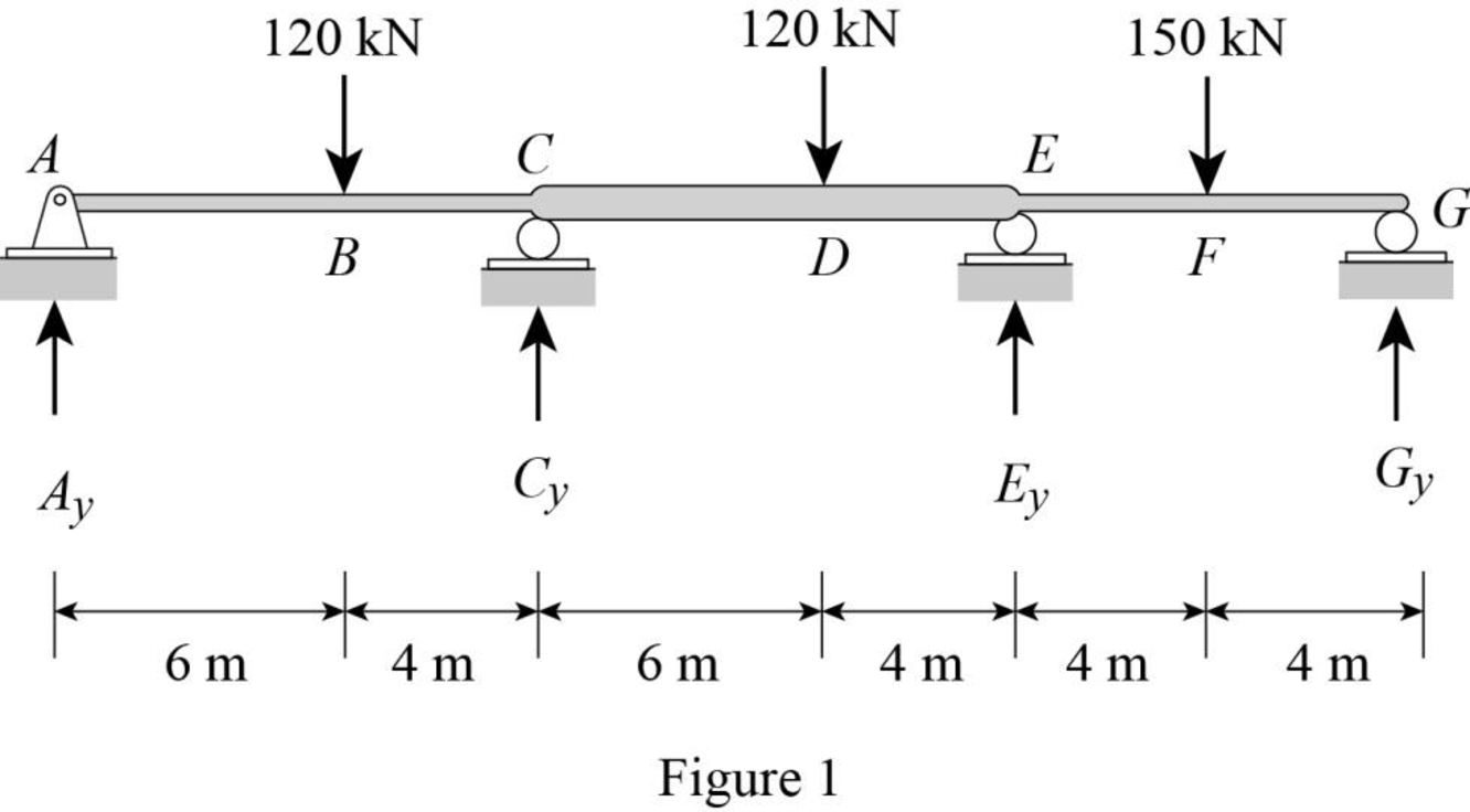
Calculate the degree of indeterminacy of the structure:
Degree of determinacy of the beam is equal to the number of unknown reactions minus the number of equilibrium equations.
The beam is supported by 5 support reactions and the number of equilibrium equations is 3.
Therefore, the degree of indeterminacy of the beam is
Select the bending moments at the supports E and C as redundant.
Let
Let
Let
Let
Let
Use beam deflection formulas:
Calculate the value of
Substitute
Substitute
Calculate the value of
Substitute
Substitute
Calculate the value of
Substitute
Substitute
Calculate the value of
Substitute
Substitute
Calculate the value of
Substitute
Substitute
Calculate the value of
Substitute
Substitute
Calculate the value of
Substitute
Substitute
Calculate the value of
Substitute
Substitute
Calculate the value of
Substitute
Substitute
The change of slope between the two tangents due to external load
Similarly Calculate the value of
The flexibility coefficient is expressed as
Calculate the value of
Sketch the settlement at supports as shown in Figure 2.
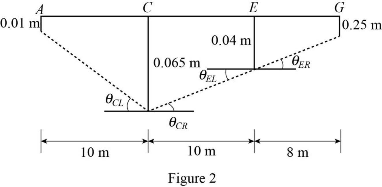
Refer to Figure 2.
Calculate the value
Calculate the value
Calculate the value
Calculate the value
Calculate the value
Calculate the value
Calculate the reactions for the given beam:
Show the compatibility Equations of the given beam as follows:
Substitute
Solve Equation (1) and Equation (2).
Sketch the span end moments and shears for span ABC, CDE, and EFG as shown in Figure 3.
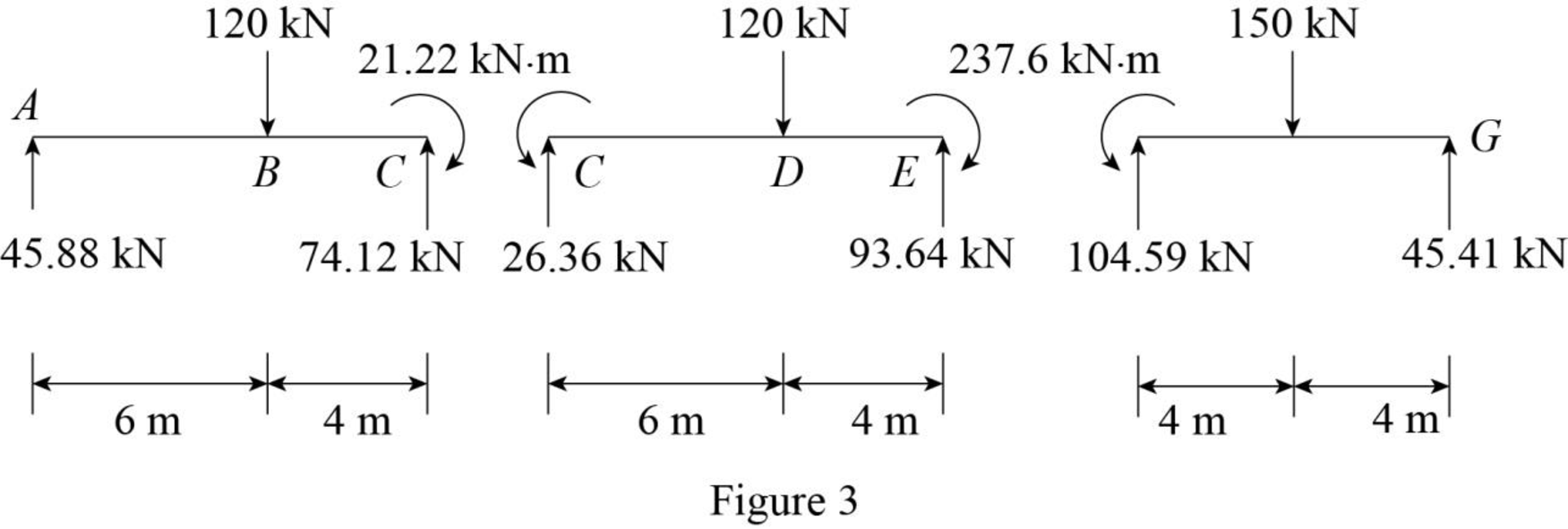
Refer to Figure 3.
Use equilibrium equations:
For span ABC,
Summation of moments of all forces about A is equal to 0.
Summation of forces along y-direction is equal to 0.
For span CDE,
Summation of moments of all forces about C is equal to 0.
Summation of forces along y-direction is equal to 0.
For span EFG,
Summation of moments of all forces about E is equal to 0.
Summation of forces along y-direction is equal to 0.
Provide the reaction at supports C and E as shown below.
Sketch the reactions for the given beam as shown in Figure 4.
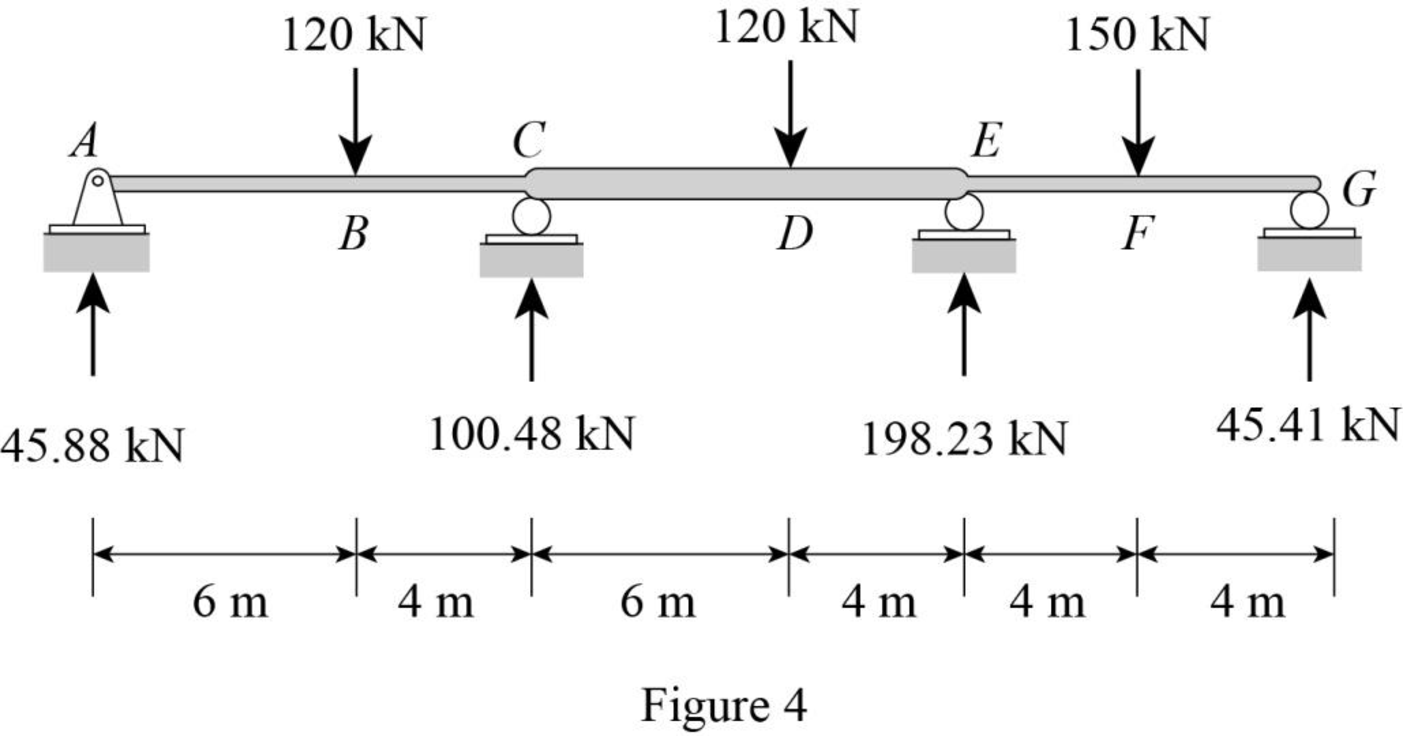
Refer to Figure 4.
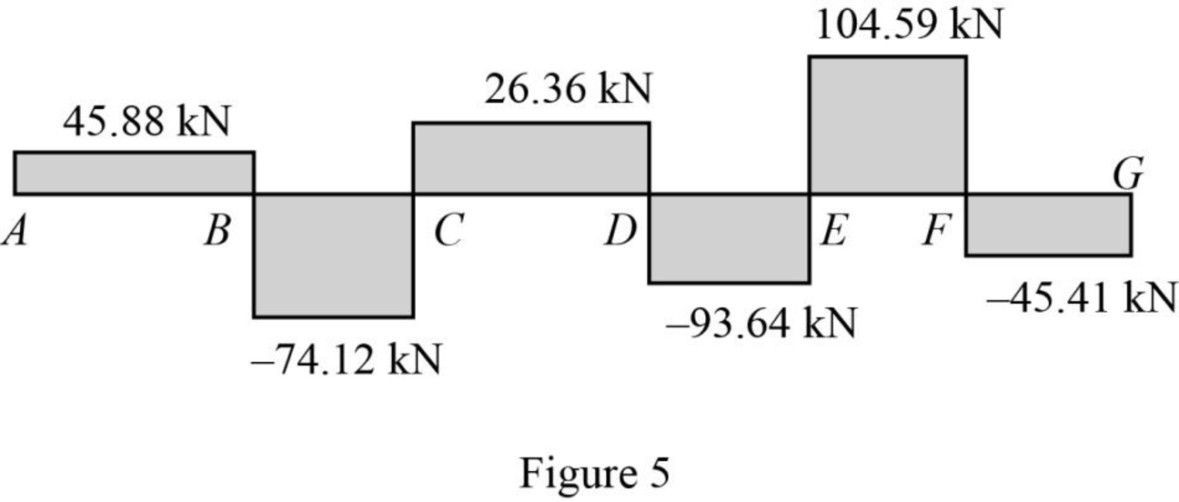
Calculate the shear force
At point A,
At point B,
At point C,
At point D,
At point E,
At point F,
At point G,
Sketch the shear diagram for the given beam as shown in Figure 5.
Refer to Figure 4.
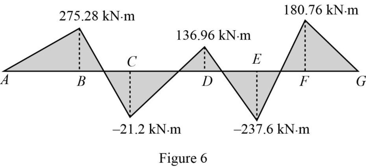
Calculate the bending moment
At point A,
At point B,
At point C,
At point D,
At point E,
At point F,
At point G,
Sketch the bending moment diagram for the given beam as shown in Figure 6.
Want to see more full solutions like this?
Chapter 13 Solutions
Structural Analysis, Si Edition (mindtap Course List)


- Question 6 options: The fourth storey of this "Dry-cleaning establishment (not using flammable solvents)" building measures 41 m x 19 m and has a public corridor. Determine the following dimensions, in millimetres (mm) The minimum width of its ramp, if it is sloped at 6°. Please give your answer to the nearest millimetre. The minimum width of its egress doors for Suite D (measuring 6 m × 4 m, ignored the elevator). Please give your answer to the nearest millimetre. The minimum width of its corridor. Please give your answer to the nearest millimetre. The minimum width of its ramp, if it is sloped at 13°. Please give your answer to the nearest millimetre.arrow_forwardFor the exposing building face marked (XX) of this unsprinklered 'Beauty parlours' building, please determine the following. justify THE answer in your hand-written solution.arrow_forwardIf the angle for the sloped glazing below is 45°, is it considered part of the roof or part of the wall? justify the answer with appropriate and detailed OBC references.arrow_forward
- Determine the state of stress acting at point E. Show the results on a differential elementat this point.arrow_forwardConsider the structure shown in the following figure, which includes two identical towers, a main cable whose unstretched length is 110 m handing between them, and two side cables with negligible weights (so that they can be modeled as massless springs). The side cables are pretentioned so that the net horizontal force on a tower iszero. The mass per unit length of the main cable is 10 kg/m and EAo = 1000KN. Thehorizontal distance between the two towers is 100 m. The angle del is 60°. By design the total horizontal load on each tower is zero. Find A)The horizontal and vertical loads exerted on each tower by the main cable B)The minimum mass M of the counter weights. Note that the counter weights are blocked from moving in the horizontal directionarrow_forward4th Order Rurka-Kutta Method This assignment will expand your skills on using Excel to perform some numerical analyses and plot your results. It is a means to familiarize you more with basic features in the spreadsheet. Preliminaries: a. Start a new file called R-K.xlsx (for this exercise, you may use the work you did in class but please be careful not to delete what you already have) b. Plan ahead Exercise 1: Using the 4" Order Ruga-Kutta Method that we recently learned, evaluate the following ordinary differential equation (ODE): dx f(t, x) = = x+t² dt At the initial position, X= 0, the time is = 0.1 minutes. Using a step size of, h = 0.05, what is the time spent to reach a position that is equal to 17 (Hint: use a O and b 1) Exercise 2 Using the 4th Order Ruga-Kutta Method, solve the following problem: The concentration of a certain non-reactive (conservative) chemical is given as a function of time by: de f(t,c) = = 30-3c Where c is the concentration and t is time. At the initial…arrow_forward
- What percentage of all communication is screened out or changed by the receiver?”arrow_forwardIn testing a certain kind or truck tire over rugged terrain, it is found that 20% of the trucks fail to complete the test run without a blowout. Of the next 13 trucks tested, find the probability that (a) from 2 to 6 have blowouts, (b) fewer than 4 have blowouts, and (c) more than 5 have blowouts. Click here to view page 1 of the table of binomial probability sums. Click here to view page 2 of the table of binomial probability sums. (a) The probability that from 2 to 6 trucks have blowouts is (Round to four decimal places as needed.)arrow_forwardA project requires 125 cubic yards of concrete sidewalk to be placed, for which 165 workhours have been budgeted. The latest weekly progress report shows that 78 cubic yards have been placed and 103 workhours have been expended to date. What is the status of the concrete placement? Significantly under budget. On budget. Significantly over budget. Status cannot be determined with information supplied.arrow_forward
- Refer to exhibit #098. At what depth was water encountered?arrow_forwardWhat is the reaction moment at A for the frame shown? a. 222.1 k-ft b. 107.8 k-ft c. 20.8 k-ft d. 23.25 k-ftarrow_forward“When a conflict exists between the project floor plans and detailed material schedule relative to size or number, which of the following usually governs in typical order of precedence?arrow_forward
