
Concept explainers
Calculate the support reactions for the given structure using method of consistent deformation.
Sketch the shear and bending moment diagrams for the given structure.
Answer to Problem 38P
The vertical reaction at B is By=25.5 k↑_.
The vertical reaction at D is Dy=41.2 k↑_.
The vertical reaction at E is Ey=18.3 k↑_.
The moment at E is ME=56 k-ft (↻)_.
Explanation of Solution
Given information:
The structure is given in the Figure.
Apply the sign conventions for calculating reactions, forces and moments using the three equations of equilibrium as shown below.
- For summation of forces along x-direction is equal to zero (∑Fx=0), consider the forces acting towards right side as positive (→+) and the forces acting towards left side as negative (←−).
- For summation of forces along y-direction is equal to zero (∑Fy=0), consider the upward force as positive (↑+) and the downward force as negative (↓−).
- For summation of moment about a point is equal to zero (∑Mat a point=0), consider the clockwise moment as positive when moment taken from left and the counter clockwise moment as positive when moment taken from right.
- Consider the positive sign indicates the clockwise moment the negative sign indicates the counterclockwise moment.
Calculation:
Sketch the free body diagram of the beam as shown in Figure 1.
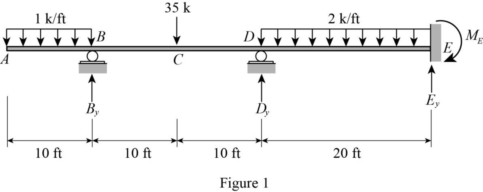
Refer Figure 1.
Find the degree of indeterminacy of the structure:
Degree of determinacy of the beam is equal to the number of unknown reactions minus the number of equilibrium equations.
The beam is supported by 4 support reactions and the number of equilibrium equations is 2.
Therefore, the degree of indeterminacy of the beam is i=2.
Select the vertical reaction By and Dy at the supports B and D as redundant.
Release the support B and D and consider the notation of moments due to external load as MO.
Sketch the free body diagram of primary beam subjected to external loading without support B and D as shown in Figure 2.
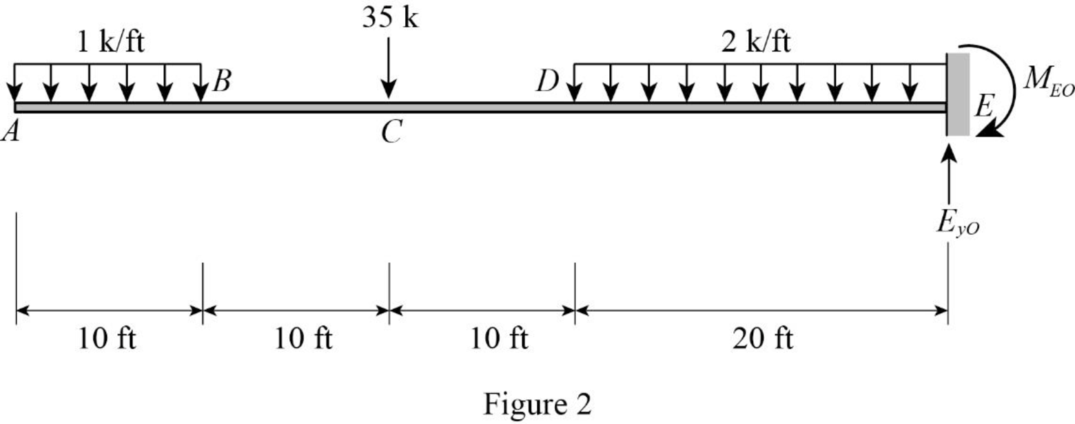
Refer Figure 2.
Find the reactions at the supports without considering support B and D using equilibrium equations:
Summation of moments of all forces about E is equal to 0.
∑ME=0MEO−1(10)(102+40)−35(30)−2(20)(202)=0MEO=1,900 k-ft (↻)
Summation of forces along y-direction is equal to 0.
+↑∑Fy=0EyO−1(10)−35−2(20)=0EyO=85 k (↑)
For unit value of the unknown redundant Dy:
Consider the notation of moments due to external load as mD.
Sketch the free body diagram of primary beam Subjected to unit value of redundant Dy as shown in Figure 3.
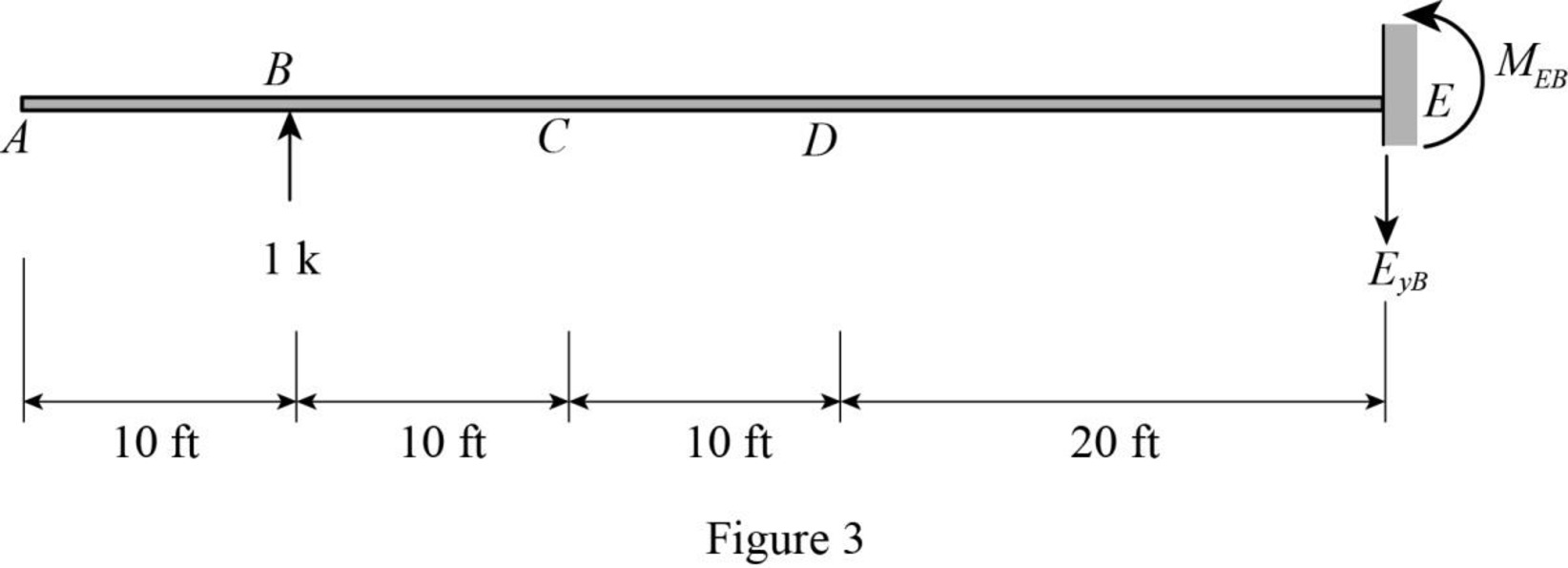
Refer Figure 3.
Find the support reaction and moment at E when 1 k vertical load applied at B.
Summation of moments of all forces about A is equal to 0.
∑ME=0MEB=1(40)MEB=40 k-ft (↺)
Summation of forces along y-direction is equal to 0.
+↑∑Fy=0−EyB+1=0EyB=1 k (↓)
For unit value of the unknown redundant By:
Consider the notation of moments due to external load as mB.
Sketch the free body diagram of primary beam Subjected to unit value of redundant By as shown in Figure 4.
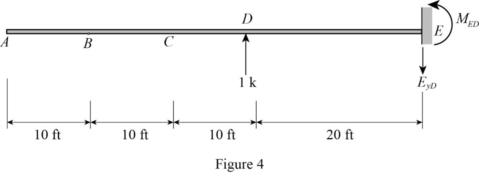
Refer Figure 4.
Find the support reaction and moment at E when 1 k vertical load applied at D.
Summation of moments of all forces about E is equal to 0.
∑MD=0MED=1(20)MED=20 k-ft (↺)
Summation of forces along y-direction is equal to 0.
+↑∑Fy=0−EyD+1=0EyD=1 k (↓)
Find the moment equation of the beam for different sections on the beam.
Consider a section XX in the portion AB of the primary structure at a distance of x from A.
Refer Figure 1.
Draw the primary structure with section XX as shown in Figure 5.
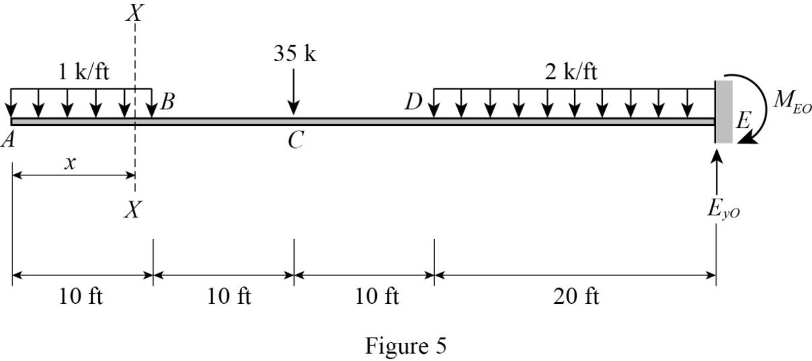
Refer Figure 5.
Portion AB.
Consider origin as A. (0≤x≤10 ft).
Find the moment at section XX in the portion AB as shown in Figure 5.
MO=1(x)(x2)=x22
Similarly calculate the moment of the remaining section in the external loading and redundant loading structures.
Tabulate the moment equation of different segment of beam as in Table 1.
| Segment | x-coordinate | MO (k-ft) | mBY (k-ft/k) | mDY (k-ft/k) | |
| Origin | Limits (ft) | ||||
| AB | A | 0−10 | x22 | 0 | 0 |
| BC | E | 10−20 | 1(10)(x−102) | −1(x−10) | 0 |
| CD | G | 20−30 | 1(10)(x−5)+35(x−20) | −1(x−10) | 0 |
| DE | D | 30−50 | [1(10)(x−5)+35(x−20)+(x−30)2] | −1(x−10) | −1(x−30) |
The vertical deflection at point B due to external loading is ΔBO, vertical deflection at point D due to external loading is ΔDO, and the flexibility coefficient representing the deflection at B due to unit value of redundant By is fBB, the redundant Dy is fDD, and the both redundant By and Dy is fBD=fDB.
Calculate the value of ΔBO using the equation as follows:
ΔBO=Σ∫MOmBYEIdx=1EI{∫100(x22)(0)dx+∫2010[1(10)(x−102)][−1(x−10)]dx+∫3020[1(10)(x−5)+35(x−20)][−1(x−10)]dx+∫5030[1(10)(x−5)+35(x−20)+(x−30)2][−1(x−10)]dx}=1EI[0−5,833.33−60,000−753,333.33]=−819,166.67EI k-ft3
Calculate the value of ΔDO using the equation as follows:
ΔDO=Σ∫MOmDYEIdx=1EI{∫100(0)dx+∫2010(0)dx+∫3020(0)dx+∫5030[1(10)(x−5)+35(x−20)+(x−30)2][−1(x−30)]dx}=1EI[0+0+0−280,000]=−280,000EI k-ft3
Calculate the value of fBB using the equation as follows:
fBB=Σ∫m2BYEIdx=1EI{∫100(0)2dx+∫2010[−1(x−10)]2dx+∫3020[−1(x−10)]2dx+∫5030[−1(x−10)]2dx}=1EI[0+333.33+2,333.33+18,666.67]=−21,333.33EI k-ft3/k
Calculate the value of fDD using the equation as follows:
fDD=Σ∫m2DYEIdx=1EI{∫100(0)2dx+∫2010(0)2dx+∫3020(0)2dx+∫5030[−1(x−30)]2dx}=1EI[0+0+0+2,666.67]=2,666.67EI k-ft3/k
Calculate the value of fFG using the equation as follows:
fBD=fDB=Σ∫mBYmBYEIdx=1EI{∫100(0)dx+∫2010(0)dx+∫3020(0)dx+∫5030[−1(x−10)][−1(x−30)]dx}=1EI[0+0+0+,666.67]=6,666.67EI k-ft3/k
Find the reactions and moment:
Find the horizontal and vertical reaction at F and G.
Show the first compatibility Equation as follows:
ΔBO+fBBBy+fBDDy=0
Substitute −819,166.67EI k-ft3 for ΔBO, 21,333.33EI k-ft3 for fBB, and 6,666.67EI k-ft3/k for fBD.
−819,166.67EI +(21,333.33EI)By+(6,666.67EI)Dy=021,333.33By+6,666.67Dy=819,166.67 (1)
Show the second compatibility Equation as follows:
ΔDO+fDBBy+fDDDy=0
Substitute −280,000EI k-ft3 for ΔDO, 6,666.67EI k-ft3/k for fDB, and 2,666.67EI k-ft3/k for fDD.
−280,000EI+(6,666.67EI)By+(2,666.67EI)Dy=06,666.67By+2,666.67Dy=280,000 (2)
Solve Equation (1) and (2).
By=25.5 k (↑)Dy=41.2 k (↑)
Find the vertical reaction at E.
Summation of forces along y-direction is equal to 0.
+↑∑Fy=0By+Dy+Ey=1(10)+35+(2)(20)25.5+41.2+Ey=85Ey=18.3 k (↑)
Find the moment at E.
Summation of moments of all forces about E is equal to 0.
∑ME=0ME−1(10)(102+40)−35(30)−2(20)(202)+(25.5×40)+(41.2×20)=0ME=56 k-ft (↻)
Therefore, the vertical reaction at B is By=25.5 k↑_.
Therefore, the vertical reaction at D is Dy=41.2 k↑_.
Therefore, the vertical reaction at E is Ey=18.3 k↑_.
Therefore, the moment at E is ME=56 k-ft (↻)_.
Sketch the free body diagram with support reactions of the beam as shown in Figure 6.
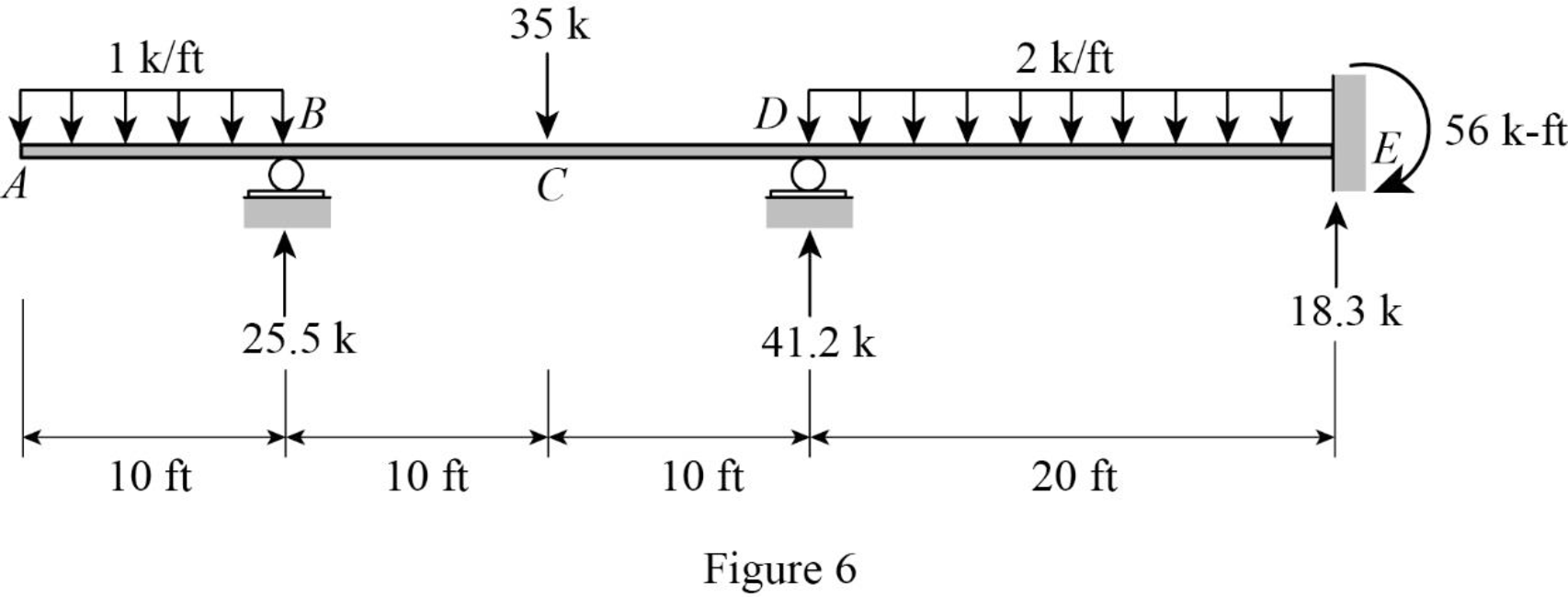
Refer Figure 6,
Find the shear force (S) for the given beam:
For span AB,
At point A.
SA=0
At point B, (negative side):
S−B=−1(10)=−10 k
For span BD,
At point B, (positive side):
S+B=−10+25.5=15.5 k
At point C, (positive side):
S+C=15.5 k
At point C, (negative side):
S−C=15.5−35=−19.5 k
At point D, (negative side):
S−D=−19.5 k
For span DF,
At point D, (positive side):
S+D=−19.5+41.2=21.7 k
At point E, (negative side):
S−E=21.7−2(20)=−18.3 k
At point E, (positive side):
S+E=−18.3+18.3=0
Sketch the shear diagram for the given beam as shown in Figure 7.
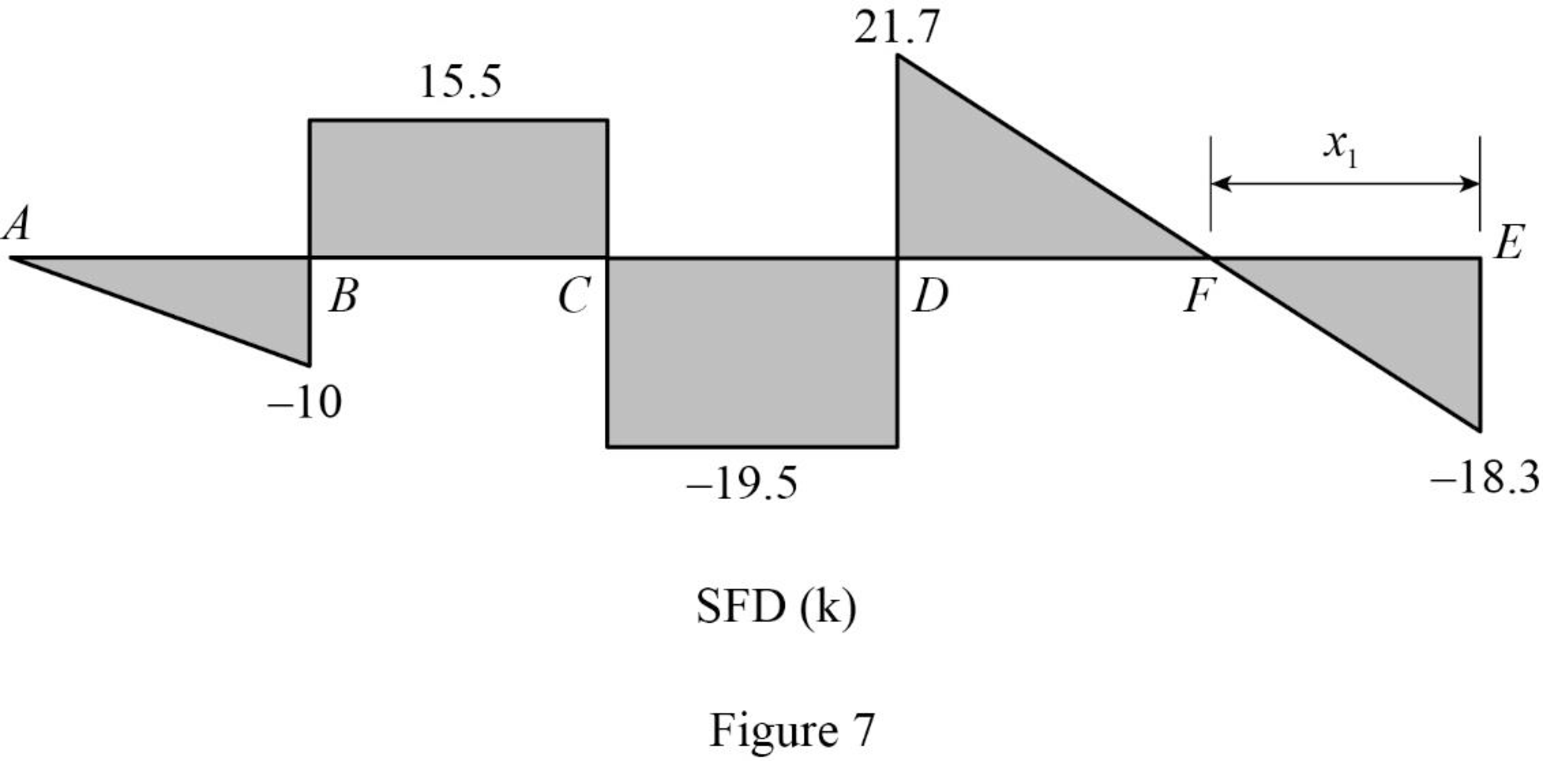
Refer Figure 7.
The points of zero shear as F.
Find the point of zero shear force from E.
18.3−2(x1)=SF018.3−2(x1)=02x1=18.3x1=9.15 ft
Refer Figure 6.
Find the bending moment (M) for the beam:
For span AB,
At point A, (free end)
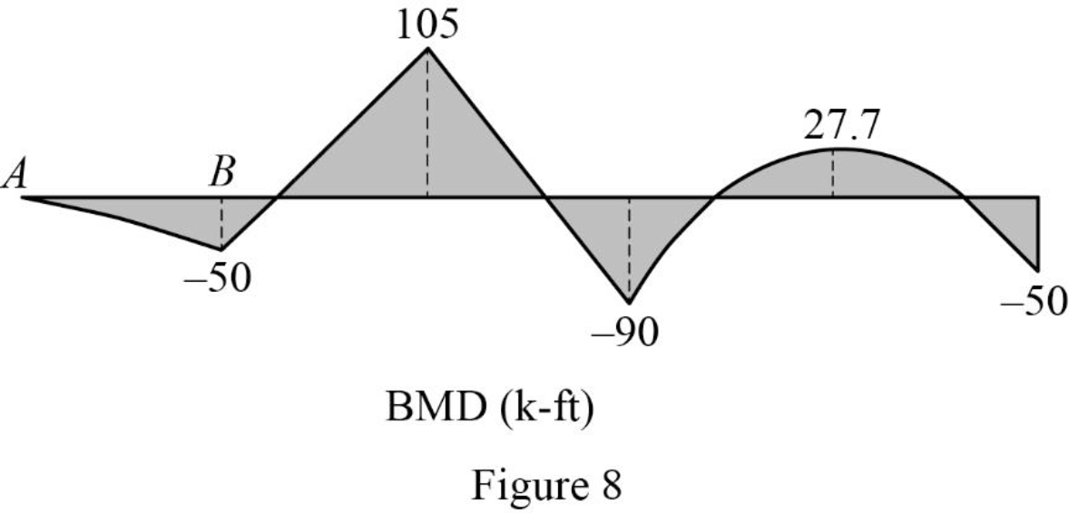
MA=0
At point B,
MB=−1(10)(102)=−50 k-ft
At point C,
MC=−1(10)(15)+25.5(10)=105 k-ft
At point D,
MD=−1(10)(25)+25.5(20)−35(10)=−90 k-ft
At point F,
MF=2(9.15)(9.152)−56=27.7 k-ft
At point E,
ME=56 k-ft
Sketch the bending moment diagram for the given beam as shown in Figure 8.
Want to see more full solutions like this?
Chapter 13 Solutions
Structural Analysis, SI Edition


- Estimate the material quantities (cement, sand, gravel, and steel reinforcement) required for constructing 120 m concrete channel of the following typical cross section, concrete mix of 1:1.5:3 and thickness of 20 cm. Figure (1) Figure (1) 12250- 16300arrow_forwarda) A 14-ft. tall and12-ft.-8-in. long fully grouted reinforced masonry wall is constructed of 8-in.CMU. It is to be analyzed for out-of-plane loading. Construct thenP -nM curves for the wallwith the following three vertical reinforcement scenarios: (1) 10 No. 6 bars at 16 in. spacing,(2) 10 No. 5 bars at 16 in. spacing, and (3) 7 No. 4 bars at 24 in. spacing. The steel is Grade60 with a modulus of elasticity of 29,000 ksi, and the masonry has a compressive strength of2,000 psi. You may use Excel or Matlab to construct the curves. Also, show the maximumnPallowed by the code for each case.(b) For each of the above reinforcement scenarios, determine the maximum axial loads that arepermitted for the tension-controlled condition and transition condition.(c) Discuss how the amount of vertical reinforcement affects thenPn-Mn curve.arrow_forwardYOU HAVE SET YOUR LEVEL UP AND ARE UTILIZING CP-101 ELEVATION FOR YOUR BENCHMARK AND HAVE THE FOLLOWING READING:CP-101=6.02YOUR FORM ELEVATION READINGS ("ATTACHED")( BEGINNING AT THE NORTHEAST BUILDING CORNER)AND WORKING IN A CLOCKWISE DIRECTION CHECKING THE BUILDING CORNER FORMSARE AS FOLLOWS: (CALCULATE THE ELEVATIONS OF 1-6 BELOW) 1. NE COR. = 1.152. SE COR. = 1.153. SW COR. = 1.354. (N) SW COR. = 1.155. INTERIOR = 1.306. NW COR. = 1.15arrow_forward
- a) A 14-ft. tall and12-ft.-8-in. long fully grouted reinforced masonry wall is constructed of 8-in.CMU. It is to be analyzed for out-of-plane loading. Construct thenP -nM curves for the wallwith the following three vertical reinforcement scenarios: (1) 10 No. 6 bars at 16 in. spacing,(2) 10 No. 5 bars at 16 in. spacing, and (3) 7 No. 4 bars at 24 in. spacing. The steel is Grade60 with a modulus of elasticity of 29,000 ksi, and the masonry has a compressive strength of2,000 psi. You may use Excel or Matlab to construct the curves. Also, show the maximumnPallowed by the code for each case.(b) For each of the above reinforcement scenarios, determine the maximum axial loads that arepermitted for the tension-controlled condition and transition condition.(c) Discuss how the amount of vertical reinforcement affects thenPn - Mn curve.arrow_forwardIf you could help me answer these questions in matlab that would be great, I provided an additional picture detailing what the outcome should look like.arrow_forwardA fully grouted reinforced masonry wall is to be constructed of 8-in. CMU. The wall height is 18feet. It is assumed to be simply supported. The wall is to be designed for an out-of-plane seismicload of 52 lbs./ft.2, which can act in either direction. The wall also supports a roof dead load of600 lbs./ft. and a roof live load of 300 lbs./ft. along the wall length. The roof loads have aneccentricity of 2.5 inches. Since there is seismic load, load combinations (6) and (7) in Chapter 2of ASCE 7-22 should be considered. In these two load combinations,horizontal seismic loadhE =andvertical seismic loadvE = . You may ignorevE in this problem for simplicity. The masonryhas a specified compressive strength of 2,500 psi. (a) Use the strength design provisions of TMS402 to determine the size and spacing of the vertical bars needed. Use the P-δ analysis method inSection 9.3.4.4.2 of TMS 402 to determine Mu. (b) Repeat the design using the momentmagnification method in Section 9.3.4.4.3 instead.arrow_forward
- The factor of safety for tipping of the concrete dam is defined as the ratio of the stabilizing moment due to the dam's weight divided by the overturning moment about OO due to the water pressure (Figure 1). Suppose that aa = 5 mm , dd = 2 mm , hh = 7 mm . The concrete has a density of ρconcρconc = 2.5 Mg/m3Mg/m3 and for water ρwρw = 1 Mg/m3Mg/m3arrow_forwardcan you answer both plss, i will give u a likearrow_forward*1-4. The hollow core panel is made from plain stone concrete. Determine the dead weight of the panel. The holes each have a diameter of 100 mm. 200 mm 300 mm 300 mm 300 mm 300 mm 300 mm Prob. 1-4 300 mm 4 marrow_forward
- derive the expressions for V and M, and draw the shear forceandbendingmomentdiagrams.Neglecttheweightofthebeam.arrow_forwarda. Draw trajectories of approximately 8 to 11 vehicles moving on a one way 1-lane road with different time-varying speeds. b. Consider a time-space window in the time-space diagram of part (a). See below. Denote the number of vehicles passing BD, DC, AC, and AB respectively as n1, N2, N3, and n4. Write an equation relating n₁, N2, N3, and n4 to each other. What is the physical intuition of this equation? Please elaborate. X 4 X. n4 n3 с n2 X1 D B n1 t c. Using density (k) definition at time instances t₁ and t₂ and flow (q) definition at locations X1 and X2, rewrite equation of interest in part (b) to demonstrate KAB-KCD 9BD-9AC + t₂-t1 x2-x1 = 0. d. What will be the equation in part (c), in case of x2 → x1 and t₂ → t₁.arrow_forwardConsider a city center where the traffic conditions are described by a Macroscopic Fundamental Diagram (MFD) of network outflow (g- rate of trips finished) vs. accumulation (n- number of cars) with a trapezoidal shape, as shown in the figure below. The values of the parameters are: • • maximum trip completion rate gmax=100 [veh/min] critical accumulations ncr1=1000 [veh] and ncr2=1500 [veh] jam accumulation njam=4000 [veh]. gmax ncr1 ncr2 njam There are two types of demands in the morning peak hour (7-8am): trips generated from outside the city center with rate q1=80 [veh/min], and trips generated from within the city center with rate q2=50 [veh/min]. In addition, a perimeter traffic control, u, is available that only restricts vehicles entering the city from outside. If at 7am there are already no=500 [veh] in the city center: a. Write the dynamic equations (mass conservation equation) in a continuous form for the center of the city. b. Convert the continuous dynamic into the discrete…arrow_forward
