
EBK ELECTRIC MOTOR CONTROL
10th Edition
ISBN: 9780100784598
Author: Herman
Publisher: YUZU
expand_more
expand_more
format_list_bulleted
Videos
Textbook Question
Chapter 13, Problem 1SQ
Draw a simple circuit showing how a red pilot light is energized when a limit switch is operated by a moving object.
Expert Solution & Answer
To determine
Draw a simple circuit to show how a red pilot light is energized by a moving object.
Explanation of Solution
Limit switch is a device used to convert mechanical motion into an electrical signal to switch circuits.
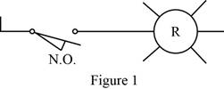
Refer to Figure 1, which shows that the symbol of limit switch is in normally open condition.
When the moving object or moving machine strikes on the operating lever of the limit switch, then the position of the switch becomes normally closed condition. Therefore, the switch gets actuated and the red pilot light is energized.
Conclusion:
Thus, a simple circuit is drawn for a red pilot light by a moving object.
Want to see more full solutions like this?
Subscribe now to access step-by-step solutions to millions of textbook problems written by subject matter experts!
Students have asked these similar questions
electric plants
do for hand writing
A lighting load of 600 kW and a motor load of 707 kW at 0.707 p.f lagging are supplied by
two alternators running in parallel. One machine supplies 900 kW at 0.9 p.f lagging. Find the load
sharing and p.f of second machine?
Please draw out the circuits
Chapter 13 Solutions
EBK ELECTRIC MOTOR CONTROL
Ch. 13 - Draw a simple circuit showing how a red pilot...Ch. 13 - Prob. 2SQCh. 13 - What is the advantage of a photodiode in a...Ch. 13 - What type of photodetector is often used in...Ch. 13 - What do Hall effect sensors detect?Ch. 13 - Hall effect sensors do not depend on...Ch. 13 - Prob. 7SQCh. 13 - Prob. 8SQCh. 13 - Prob. 9SQCh. 13 - How is it possible for the miscroswitch to change...
Knowledge Booster


Learn more about
Need a deep-dive on the concept behind this application? Look no further. Learn more about this topic, electrical-engineering and related others by exploring similar questions and additional content below.Similar questions
- Q2 but when you get to part 3, can you please draw it outarrow_forwardplease solve manually. I need the drawing and the values too. Thank you!arrow_forwardTwo alternators, Y-connected 6.6 kV supply a load of 3000 kW at 0.8 p.f lagging. The synchronous mpedance of first alternator is (0.5+j10) Q/ph and second alternator is (0.4+j12) /ph. First alternator delivers 150 amp at 0.875 lag p.f. The two alterators are shared load equally. Determine the current, p.f., induced e.m.f, load angel, and maximum developed power of each alternator?arrow_forward
- A domestic load of 2300 kW at 0.88 p.f lagging and a motors load of 3400 kW at 0.85 p.f lagging are supplied by two alternators operating in parallel. If one alternator is delivering a load of 3300 kW at 0.9 p.f lagging, what will be the output power and p.f of the other alternator?arrow_forwardDetermine the value of Rr that necessary for the circuit in Fig.(2) to operate as an oscillator and then determine the frequency of oscillation. 0.001 F 0.001 F 0.001 F R₁ • 10 ΚΩ R₁ 10 k R • 10 ΚΩarrow_forward(a) For the circuit shown in Figure Q3(a) (RFC and Cc are forbias) (i) (ii) Draw the AC small signal equivalent circuit of the oscillator. From this equivalent circuit derive an equation for fo and the gain condition for the oscillations to start. VDD www RG eee RFC H Cc 北 5 C₁ L 000 C₂ Voarrow_forward
- Please solve this question step by step handwritten solution and do not use chat gpt or any ai toolsfor part ii) you may need to use nodal analysisarrow_forward12.1. Find the steady-state response vo (t) for the network. 00000- 1Ω ww 12 cos(t) V + www 202 1 H 202 1 F + 1Ω νο -arrow_forwardA Three-phase, 12 pole, Y-connected alternator has 108 slots and 14 conductors per slot. The windings are (5/6 th) pitched. The flux per pole is 57 mWb distributed sinusoidally over the pole. If the machine runs at 500 r.p.m., determine the following: (a) The frequency of the generated e.m.f., (b) The distribution factor, (c) The pitch factor, and (d) The phase and line values of the generated e.m.f.?arrow_forward
- Two 3-ph, 6.6 kV, Y-connected, alternators supply a load of 3000 kW at 0.8 p.f. lagging. The synchronou impedance per phase of machine A is (0.5+110) and that of machine B is (0.4 +J12) . The excitation of machine A adjusted so that it delivers 150 A. The load is shared equally between the machines. Determine the armature curre p.f., induced e.m.f., and load angle of each machine?arrow_forwardName the circuit below? The output voltage is initially zero and the pulse width is 200 μs. Find the Vout and draw the output waveform? +2.5 V V 247 -2.5 V C 0.01 F Ri W 10 ΚΩarrow_forwardPlease work outarrow_forward
arrow_back_ios
SEE MORE QUESTIONS
arrow_forward_ios
Recommended textbooks for you

 Electricity for Refrigeration, Heating, and Air C...Mechanical EngineeringISBN:9781337399128Author:Russell E. SmithPublisher:Cengage Learning
 EBK ELECTRICAL WIRING RESIDENTIALElectrical EngineeringISBN:9781337516549Author:SimmonsPublisher:CENGAGE LEARNING - CONSIGNMENT
Electricity for Refrigeration, Heating, and Air C...
Mechanical Engineering
ISBN:9781337399128
Author:Russell E. Smith
Publisher:Cengage Learning
EBK ELECTRICAL WIRING RESIDENTIAL
Electrical Engineering
ISBN:9781337516549
Author:Simmons
Publisher:CENGAGE LEARNING - CONSIGNMENT
Pressure Sensors with Display; Author: Balluff Worldwide;https://www.youtube.com/watch?v=HqAV2xjCLxE;License: Standard Youtube License