
Mechanics of Materials
11th Edition
ISBN: 9780137605460
Author: Russell C. Hibbeler
Publisher: Pearson Education (US)
expand_more
expand_more
format_list_bulleted
Concept explainers
Videos
Textbook Question
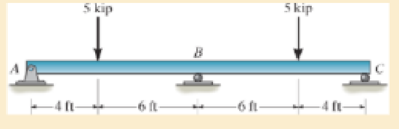
Chapter 12.8, Problem 112P
Determine the reaction at the supports, then draw the shear and moment diagrams. El is constant.
Expert Solution & Answer
Want to see the full answer?
Check out a sample textbook solution
Students have asked these similar questions
Homework#7
Computing Angles of Rotation and Angles of Tilt
In each of the following problems, the axis of a hole is shown in a rectangular solid. In
order to position the hole axis for drilling, the angle of rotation and the angle of tilt must be
determined. Compute angles to the nearer minute in triangles with customary unit sides.
Compute angles to the nearer hundredth degree in triangles with metric unit sides.
a. Compute the angle of rotation, R.
b. Compute the angle of tilt,
T.
7. Given: H= 2.600 in.
L = 2.400 in.
a.
W= 1.900 in.
8. Given: H= 55.00 mm
b.
Use this figure for #7 and #8.
AXIS OF HOLE
L 48.00 mm
W= 30.00 mm
H
a.
b.
9. Given: H = 4.750 in.
L = 4.000 in.
W= 3.750 in.
a.
10. Given: H=42.00 mm
b.
L37.00 mm
W = 32.00 mm
a.
b.
11. Given: H = 0.970 in.
L = 0.860 in.
W= 0.750 in.
a.
12. Given: H= 22.00 mm
L 18.00 mm
=
W = 15.00 mm
a.
b.
Use this figure for #9 and #10.
ZR
AXIS OF HOLE
Use this figure for #11 and #12.
H
b.
L
AXIS OF HOLE
T
This is a tilt and rotation question. Here are notes attached for reference. I prefer handwritten solutions. ONLY UPLOAD A SOLUTION IF YOU ARE SURE ABOUT THE ANSWER PLEASE. I prefer handwritten solutions.
Chapter 12 Solutions
Mechanics of Materials
Ch. 12.2 - Determine the slope and deflection of end A of the...Ch. 12.2 - Determine the slope and deflection of end A of the...Ch. 12.2 - Determine the slope of end A of the cantilevered...Ch. 12.2 - Determine the maximum deflection of the simply...Ch. 12.2 - Determine the maximum deflection of the simply...Ch. 12.2 - Determine the slope of the simply supported beam...Ch. 12.2 - An L2 steel strap having a thickness of 0.125 in....Ch. 12.2 - The L2 steel blade of the band saw wraps around...Ch. 12.2 - A picture is taken of a man performing a pole...Ch. 12.2 - A torque wrench is used to tighten the nut on a...
Ch. 12.2 - The pipe can be assumed roller supported at its...Ch. 12.2 - Determine the equations of the elastic curve for...Ch. 12.2 - Determine the equations of the elastic curve using...Ch. 12.2 - Determine the maximum deflection of the solid...Ch. 12.2 - Determine the equation of the elastic curve using...Ch. 12.2 - Determine the equations of the elastic curve using...Ch. 12.3 - The shaft supports the two pulley loads shown....Ch. 12.3 - Determine the equation of the elastic curve, the...Ch. 12.3 - Determine the equation of the elastic curve and...Ch. 12.3 - Determine the maximum deflection of the...Ch. 12.3 - Prob. 45PCh. 12.3 - Prob. 46PCh. 12.3 - Prob. 47PCh. 12.3 - Prob. 48PCh. 12.4 - Determine the slope and deflection of end A of the...Ch. 12.4 - Determine the slope and deflection of end A of the...Ch. 12.4 - Determine the slope and deflection of end A of the...Ch. 12.4 - Determine the slope and deflection at A of the...Ch. 12.4 - Prob. 11FPCh. 12.4 - Determine the maximum deflection of the simply...Ch. 12.4 - Determine the slope and deflection at C. El is...Ch. 12.4 - Prob. 54PCh. 12.4 - The composite simply supported steel shaft is...Ch. 12.4 - Determine the maximum deflection of the...Ch. 12.4 - Prob. 60PCh. 12.4 - Determine the slope at A and the maximum...Ch. 12.4 - Determine the displacement of the 20-mm-diameter...Ch. 12.4 - The two force components act on the tire of the...Ch. 12.4 - Determine the slope at B and deflection at C. El...Ch. 12.4 - Prob. 79PCh. 12.5 - The W10 15 cantilevered beam is made of A-36...Ch. 12.5 - The W14 43 simply supported beam is made of A992...Ch. 12.5 - The W14 43 simply supported beam is made of A992...Ch. 12.5 - The W14 43 simply supported beam is made of A-36...Ch. 12.7 - Determine the reactions at the supports A and B,...Ch. 12.7 - Determine the reactions at the supports A, B, and...Ch. 12.7 - Determine the reactions at the supports A and B,...Ch. 12.7 - The beam has a constant E1I1 and is supported by...Ch. 12.8 - Determine the reaction at the supports, then draw...Ch. 12.9 - Determine the reactions at the fixed support A and...Ch. 12.9 - Determine the reactions at the fixed support A and...Ch. 12.9 - Determine the reactions at the fixed support A and...Ch. 12.9 - Determine the reaction at the roller B. EI is...Ch. 12.9 - Determine the reaction at the roller B. EI is...Ch. 12.9 - Determine the reaction at the roller support B if...Ch. 12.9 - Determine the reactions at the journal bearing...Ch. 12.9 - Determine the reactions at the supports, then draw...Ch. 12.9 - Determine the reactions at the supports, then draw...Ch. 12.9 - The rim on the flywheel has a thickness t, width...Ch. 12.9 - Determine the moment developed in each corner....Ch. 12 - Determine the equation of the elastic curve. Use...Ch. 12 - Draw the bending-moment diagram for the shaft and...Ch. 12 - Determine the moment reactions at the supports A...Ch. 12 - Specify the slope at A and the maximum deflection....Ch. 12 - Determine the maximum deflection between the...Ch. 12 - Determine the slope at B and the deflection at C....Ch. 12 - Determine the reactions, then draw the shear and...Ch. 12 - El is constant.Ch. 12 - Using the method of superposition, determine the...
Knowledge Booster


Learn more about
Need a deep-dive on the concept behind this application? Look no further. Learn more about this topic, mechanical-engineering and related others by exploring similar questions and additional content below.Similar questions
- Consider a constant area semi-infinite fin of a circular cross section of radius r. and thermal conductivity k. The base is maintained at T. and the surface of the fin exchanges heat by convection to an ambient fluid at T with a heat transfer coefficient h. It is desired to increase the heat transfer from the fin. The following suggestions are made: (i) doubling k, (ii) doubling ro, (iii) doubling h. Which suggestion will bring about the largest increase in heat transfer? To x h, T C A h, Tarrow_forwardA 20 cm long 304 stainless steel bar is initially at 18°C. One end of the bar is suddenly maintained at 100°C. Assuming that your finger can tolerate a 60°C temperature, what is the longest time you are willing to wait before you touch the other end? Be on the safe side and select a conservative model. h,T oil bath glass ballarrow_forwardSmall glass balls of radius 1.1 mm are cooled in an oil bath at 22°C. The balls enter the bath at 180°C and are moved through on a conveyor belt. The estimated heat transfer coefficient is 75 W/m²-ºC. What should the conveyor speed be so that the balls leave at 40°C? The length of bath is 2.5 m.arrow_forward
- Just do Questions 7, 9, 11. Here are notes attached for reference. I prefer handwritten solutions. ONLY UPLOAD A SOLUTION IF YOU ARE SURE ABOUT THE ANSWER PLEASE.arrow_forwardThis is a tilt and rotation question. Here are notes attached for reference. I prefer handwritten solutions. ONLY UPLOAD A SOLUTION IF YOU ARE SURE ABOUT THE ANSWER PLEASE. I prefer handwritten solutions.arrow_forwardA turbine blade made of a metal alloy (k = 17 W/m-K) has a length of 5.3 cm, a perimeter of 11 cm, and a cross-sectional area of 5.13 cm². The turbine blade is exposed to hot gas from the combustion chamber at 1133°C with a convection heat transfer coefficient of 538 W/m²K. The base of the turbine blade maintains a constant temperature of 450°C and the tip is adiabatic. NOTE: This is a multi-part question. Once an answer is submitted, you will be unable to return to this part. Hot gas h=538 W/m²K TL E= Turbine blade k = 17 W/m-K p=11 cm, L=5.3 cm A = 5.13cm² T=450°C Determine the temperature at the tip of the turbine blade. The temperature at the tip of the turbine blade is °C.arrow_forward
- ۲/۱ : +0 تا العنوان Ч Example 5.5 The turbine rotor of a ship has a mass of 30 tons, a radius of gyration of 600 mm and rotates at 2400 rpm in a clockwise direction when viewed from aft. The ship pitches through a total angle of 15, 7.5" above and 7.5° below the horizontal, the motion being simple harmonic and having a period of 12 sec. Determine the maximum gyroscopic couple on the holding down bolts of the turbine and the direction of yaw as the Dow rises. h2023-43-115-154 Vees 2V & Pond35. sketch the diagram for them. 147% 3-inpuls RTL-NAND having Re14502 BRO Sel: VIL VBEON 0.65V VIHAVING + 1.34V VHB VIHC Vesss: 1.142V Vine: IB RO+VBES+ 640 Vec Ret 709420 IB₁ 10.3mA Ic: Vec-VCE 5-0-2 Re 45 · 10.67-A ICCE: When A&B &C. "1" Vol No 30206 When A&B &c, "o" Uok Vec5v L.S. 5.06 4.4v VIT 94+114+1.34 -3.42 V N.ML5 V N.Mu-16u T.W= 2.75 169 N.Mu VEM VL N.ML Lex-V Re 16.41A Re ± 10.6mA Pony =69mw 37 L.S >arrow_forwardI don't know how to answer this questionarrow_forwardRequired information Consider a very long, slender rod. One end of the rod is attached to a base surface maintained at Tb, while the surface of the rod is exposed to an air temperature of 400°C. Thermocouples imbedded in the rod at locations 25 mm and 120 mm from the base surface register temperatures of 325°C and 375°C, respectively. NOTE: This is a multi-part question. Once an answer is submitted, you will be unable to return to this part. T₁ Ть T₂ x2 Air Determine the rod length (mm) for the case where the ratio of the heat transfer from a finite length fin to the heat transfer from a very long fin under the same conditions is 99 percent. The length of the rod is mm.arrow_forward
- please find Ix in mm4arrow_forward۲/۱ ∞ + : 5V ON Date AND Loaded with an oR P 5- A R Vect bov V(22)= IR, Vcc-vd 2R V(21) V(22) + Vd=" or V(z) HomeWo Vec-T 022 51-2 العنوان Example 5.5: The turbine rotor of a ship has a mass of 30 tons, a radius of gyration of 600 mm and rotates at 2400 rpm in a clockwise direction when viewed from aft. The ship pitches through a total angle of 15%, 7.5° above and 7.5° below the horizontal, the motion being simple harmonic and having a period of 12 sec. Determine the maximum gyroscopic couple on the holding down bolts of the turbine and the direction of yaw as the Dow rises. Vezi b) V225 V22 lo 21.5 2.15 U 5-0.7 K Loka (I= Vecond R 5:4.57 U 25-0-7 Tak R 5-0.7 5kr V2, Va-IR=5-2.15 -2-85 NEW G C 'WR к >arrow_forward: + ♡ +① العنوان I need a detailed drawing with explanation so A 4 ined sove in peaper 96252 Example 5.5 The turbine rotor of ship has a mass of 30 tons, a radius of gyration of 600 mm and rotates at 2400 rpm ia clockwise direction when viewed from aft. The ship pitches through a total angle of 7.5° above and 7.5° below the horizontal, the motion beingle harmonic and hav gyroscopic couple on the bow rises. ding down be a period of 12 sec. Determine the maximum of the turbine and the direction of yaw as bax r 2.01 ۳/۱arrow_forward
arrow_back_ios
SEE MORE QUESTIONS
arrow_forward_ios
Recommended textbooks for you
 Elements Of ElectromagneticsMechanical EngineeringISBN:9780190698614Author:Sadiku, Matthew N. O.Publisher:Oxford University Press
 Mechanics of Materials (10th Edition)Mechanical EngineeringISBN:9780134319650Author:Russell C. HibbelerPublisher:PEARSON
 Thermodynamics: An Engineering ApproachMechanical EngineeringISBN:9781259822674Author:Yunus A. Cengel Dr., Michael A. BolesPublisher:McGraw-Hill Education
 Control Systems EngineeringMechanical EngineeringISBN:9781118170519Author:Norman S. NisePublisher:WILEY
 Mechanics of Materials (MindTap Course List)Mechanical EngineeringISBN:9781337093347Author:Barry J. Goodno, James M. GerePublisher:Cengage Learning
 Engineering Mechanics: StaticsMechanical EngineeringISBN:9781118807330Author:James L. Meriam, L. G. Kraige, J. N. BoltonPublisher:WILEY
Elements Of Electromagnetics
Mechanical Engineering
ISBN:9780190698614
Author:Sadiku, Matthew N. O.
Publisher:Oxford University Press
Mechanics of Materials (10th Edition)
Mechanical Engineering
ISBN:9780134319650
Author:Russell C. Hibbeler
Publisher:PEARSON
Thermodynamics: An Engineering Approach
Mechanical Engineering
ISBN:9781259822674
Author:Yunus A. Cengel Dr., Michael A. Boles
Publisher:McGraw-Hill Education
Control Systems Engineering
Mechanical Engineering
ISBN:9781118170519
Author:Norman S. Nise
Publisher:WILEY
Mechanics of Materials (MindTap Course List)
Mechanical Engineering
ISBN:9781337093347
Author:Barry J. Goodno, James M. Gere
Publisher:Cengage Learning
Engineering Mechanics: Statics
Mechanical Engineering
ISBN:9781118807330
Author:James L. Meriam, L. G. Kraige, J. N. Bolton
Publisher:WILEY
Understanding Shear Force and Bending Moment Diagrams; Author: The Efficient Engineer;https://www.youtube.com/watch?v=C-FEVzI8oe8;License: Standard YouTube License, CC-BY
Bending Stress; Author: moodlemech;https://www.youtube.com/watch?v=9QIqewkE6xM;License: Standard Youtube License