
Mechanics of Materials
11th Edition
ISBN: 9780137605514
Author: Russell C. Hibbeler
Publisher: Pearson Education (US)
expand_more
expand_more
format_list_bulleted
Concept explainers
Videos
Textbook Question
Chapter 12.4, Problem 10FP
Determine the slope and deflection at A of the cantilevered beam. E = 29(103) ksi, I = 245 in4.
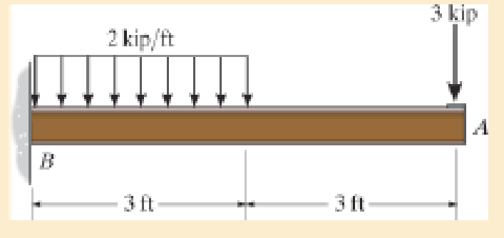
F12–10
Expert Solution & Answer
Want to see the full answer?
Check out a sample textbook solution
Students have asked these similar questions
3.) 15.40 – Collar B moves up at constant velocity vB = 1.5 m/s. Rod AB has length = 1.2 m. The incline is
at angle = 25°. Compute an expression for the angular velocity of rod AB, ė and the velocity of end A of the
rod (✓✓) as a function of v₂,1,0,0. Then compute numerical answers for ȧ & y_ with 0 = 50°.
2.) 15.12 The assembly shown consists of the straight rod ABC which passes through and is welded to the
grectangular plate DEFH. The assembly rotates about the axis AC with a constant angular velocity of 9 rad/s.
Knowing that the motion when viewed from C is counterclockwise, determine the velocity and acceleration of
corner F.
500
Q3: The attachment shown in Fig.3 is made of
1040 HR. The static force is 30 kN. Specify the
weldment (give the pattern, electrode
number, type of weld, length of weld, and leg
size).
Fig. 3
All dimension
in mm
30 kN
100
(10 Marks)
Chapter 12 Solutions
Mechanics of Materials
Ch. 12.2 - Determine the slope and deflection of end A of the...Ch. 12.2 - Determine the slope and deflection of end A of the...Ch. 12.2 - Determine the slope of end A of the cantilevered...Ch. 12.2 - Determine the maximum deflection of the simply...Ch. 12.2 - Determine the maximum deflection of the simply...Ch. 12.2 - Determine the slope of the simply supported beam...Ch. 12.2 - An L2 steel strap having a thickness of 0.125 in....Ch. 12.2 - The L2 steel blade of the band saw wraps around...Ch. 12.2 - A picture is taken of a man performing a pole...Ch. 12.2 - A torque wrench is used to tighten the nut on a...
Ch. 12.2 - The pipe can be assumed roller supported at its...Ch. 12.2 - Determine the equations of the elastic curve for...Ch. 12.2 - Determine the equations of the elastic curve using...Ch. 12.2 - Determine the maximum deflection of the solid...Ch. 12.2 - Determine the equation of the elastic curve using...Ch. 12.2 - Determine the equations of the elastic curve using...Ch. 12.3 - The shaft supports the two pulley loads shown....Ch. 12.3 - Determine the equation of the elastic curve, the...Ch. 12.3 - Determine the equation of the elastic curve and...Ch. 12.3 - Determine the maximum deflection of the...Ch. 12.3 - Prob. 45PCh. 12.3 - Prob. 46PCh. 12.3 - Prob. 47PCh. 12.3 - Prob. 48PCh. 12.4 - Determine the slope and deflection of end A of the...Ch. 12.4 - Determine the slope and deflection of end A of the...Ch. 12.4 - Determine the slope and deflection of end A of the...Ch. 12.4 - Determine the slope and deflection at A of the...Ch. 12.4 - Prob. 11FPCh. 12.4 - Determine the maximum deflection of the simply...Ch. 12.4 - Determine the slope and deflection at C. El is...Ch. 12.4 - Prob. 54PCh. 12.4 - The composite simply supported steel shaft is...Ch. 12.4 - Determine the maximum deflection of the...Ch. 12.4 - Prob. 60PCh. 12.4 - Determine the slope at A and the maximum...Ch. 12.4 - Determine the displacement of the 20-mm-diameter...Ch. 12.4 - The two force components act on the tire of the...Ch. 12.4 - Determine the slope at B and deflection at C. El...Ch. 12.4 - Prob. 79PCh. 12.5 - The W10 15 cantilevered beam is made of A-36...Ch. 12.5 - The W14 43 simply supported beam is made of A992...Ch. 12.5 - The W14 43 simply supported beam is made of A992...Ch. 12.5 - The W14 43 simply supported beam is made of A-36...Ch. 12.7 - Determine the reactions at the supports A and B,...Ch. 12.7 - Determine the reactions at the supports A, B, and...Ch. 12.7 - Determine the reactions at the supports A and B,...Ch. 12.7 - The beam has a constant E1I1 and is supported by...Ch. 12.8 - Determine the reaction at the supports, then draw...Ch. 12.9 - Determine the reactions at the fixed support A and...Ch. 12.9 - Determine the reactions at the fixed support A and...Ch. 12.9 - Determine the reactions at the fixed support A and...Ch. 12.9 - Determine the reaction at the roller B. EI is...Ch. 12.9 - Determine the reaction at the roller B. EI is...Ch. 12.9 - Determine the reaction at the roller support B if...Ch. 12.9 - Determine the reactions at the journal bearing...Ch. 12.9 - Determine the reactions at the supports, then draw...Ch. 12.9 - Determine the reactions at the supports, then draw...Ch. 12.9 - The rim on the flywheel has a thickness t, width...Ch. 12.9 - Determine the moment developed in each corner....Ch. 12 - Determine the equation of the elastic curve. Use...Ch. 12 - Draw the bending-moment diagram for the shaft and...Ch. 12 - Determine the moment reactions at the supports A...Ch. 12 - Specify the slope at A and the maximum deflection....Ch. 12 - Determine the maximum deflection between the...Ch. 12 - Determine the slope at B and the deflection at C....Ch. 12 - Determine the reactions, then draw the shear and...Ch. 12 - El is constant.Ch. 12 - Using the method of superposition, determine the...
Additional Engineering Textbook Solutions
Find more solutions based on key concepts
Computers process data under the control of sets of instructions called
Java How to Program, Early Objects (11th Edition) (Deitel: How to Program)
This optional Google account security feature sends you a message with a code that you must enter, in addition ...
SURVEY OF OPERATING SYSTEMS
CONCEPT QUESTIONS
15.CQ3 The ball rolls without slipping on the fixed surface as shown. What is the direction ...
Vector Mechanics for Engineers: Statics and Dynamics
Why is the study of database technology important?
Database Concepts (8th Edition)
Assume a telephone signal travels through a cable at two-thirds the speed of light. How long does it take the s...
Electric Circuits. (11th Edition)
17–1C A high-speed aircraft is cruising in still air. How does the temperature of air at the nose of the aircra...
Thermodynamics: An Engineering Approach
Knowledge Booster


Learn more about
Need a deep-dive on the concept behind this application? Look no further. Learn more about this topic, mechanical-engineering and related others by exploring similar questions and additional content below.Similar questions
- (read image) (answer given)arrow_forwardA cylinder and a disk are used as pulleys, as shown in the figure. Using the data given in the figure, if a body of mass m = 3 kg is released from rest after falling a height h 1.5 m, find: a) The velocity of the body. b) The angular velocity of the disk. c) The number of revolutions the cylinder has made. T₁ F Rd = 0.2 m md = 2 kg T T₂1 Rc = 0.4 m mc = 5 kg ☐ m = 3 kgarrow_forward(read image) (answer given)arrow_forward
- 11-5. Compute all the dimensional changes for the steel bar when subjected to the loads shown. The proportional limit of the steel is 230 MPa. 265 kN 100 mm 600 kN 25 mm thickness X Z 600 kN 450 mm E=207×103 MPa; μ= 0.25 265 kNarrow_forwardT₁ F Rd = 0.2 m md = 2 kg T₂ Tz1 Rc = 0.4 m mc = 5 kg m = 3 kgarrow_forward2. Find a basis of solutions by the Frobenius method. Try to identify the series as expansions of known functions. (x + 2)²y" + (x + 2)y' - y = 0 ; Hint: Let: z = x+2arrow_forward
- 1. Find a power series solution in powers of x. y" - y' + x²y = 0arrow_forward3. Find a basis of solutions by the Frobenius method. Try to identify the series as expansions of known functions. 8x2y" +10xy' + (x 1)y = 0 -arrow_forwardHello I was going over the solution for this probem and I'm a bit confused on the last part. Can you please explain to me 1^4 was used for the Co of the tubular cross section? Thank you!arrow_forward
- Blood (HD = 0.45 in large diameter tubes) is forced through hollow fiber tubes that are 20 µm in diameter.Equating the volumetric flowrate expressions from (1) assuming marginal zone theory and (2) using an apparentviscosity for the blood, estimate the marginal zone thickness at this diameter. The viscosity of plasma is 1.2 cParrow_forwardQ2: Find the shear load on bolt A for the connection shown in Figure 2. Dimensions are in mm Fig. 2 24 0-0 0-0 A 180kN (10 Markarrow_forwarddetermine the direction and magnitude of angular velocity ω3 of link CD in the four-bar linkage using the relative velocity graphical methodarrow_forward
arrow_back_ios
SEE MORE QUESTIONS
arrow_forward_ios
Recommended textbooks for you
 Elements Of ElectromagneticsMechanical EngineeringISBN:9780190698614Author:Sadiku, Matthew N. O.Publisher:Oxford University Press
 Mechanics of Materials (10th Edition)Mechanical EngineeringISBN:9780134319650Author:Russell C. HibbelerPublisher:PEARSON
 Thermodynamics: An Engineering ApproachMechanical EngineeringISBN:9781259822674Author:Yunus A. Cengel Dr., Michael A. BolesPublisher:McGraw-Hill Education
 Control Systems EngineeringMechanical EngineeringISBN:9781118170519Author:Norman S. NisePublisher:WILEY
 Mechanics of Materials (MindTap Course List)Mechanical EngineeringISBN:9781337093347Author:Barry J. Goodno, James M. GerePublisher:Cengage Learning
 Engineering Mechanics: StaticsMechanical EngineeringISBN:9781118807330Author:James L. Meriam, L. G. Kraige, J. N. BoltonPublisher:WILEY
Elements Of Electromagnetics
Mechanical Engineering
ISBN:9780190698614
Author:Sadiku, Matthew N. O.
Publisher:Oxford University Press
Mechanics of Materials (10th Edition)
Mechanical Engineering
ISBN:9780134319650
Author:Russell C. Hibbeler
Publisher:PEARSON
Thermodynamics: An Engineering Approach
Mechanical Engineering
ISBN:9781259822674
Author:Yunus A. Cengel Dr., Michael A. Boles
Publisher:McGraw-Hill Education
Control Systems Engineering
Mechanical Engineering
ISBN:9781118170519
Author:Norman S. Nise
Publisher:WILEY
Mechanics of Materials (MindTap Course List)
Mechanical Engineering
ISBN:9781337093347
Author:Barry J. Goodno, James M. Gere
Publisher:Cengage Learning
Engineering Mechanics: Statics
Mechanical Engineering
ISBN:9781118807330
Author:James L. Meriam, L. G. Kraige, J. N. Bolton
Publisher:WILEY
Solids: Lesson 53 - Slope and Deflection of Beams Intro; Author: Jeff Hanson;https://www.youtube.com/watch?v=I7lTq68JRmY;License: Standard YouTube License, CC-BY