
Mechanics of Materials
11th Edition
ISBN: 9780137605460
Author: Russell C. Hibbeler
Publisher: Pearson Education (US)
expand_more
expand_more
format_list_bulleted
Concept explainers
Videos
Textbook Question
Chapter 12.2, Problem 1FP
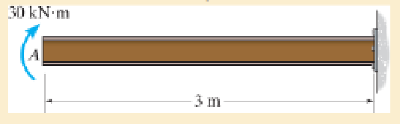
Determine the slope and deflection of end A of the cantilevered beam. E = 200 GPa and I = 65.0(106) mm4.
F12–1
Expert Solution & Answer

Learn your wayIncludes step-by-step video

schedule09:07
Students have asked these similar questions
Complete the following problems. Show your work/calculations, save as.pdf and upload to the
assignment in Blackboard.
missing information to present a completed program. (Hint: You may have to look up geometry
for the center drill and standard 0.5000 in twist drill to know the required depth to drill).
1. What are the x and y dimensions for the center position of holes 1,2, and 3 in the part shown in
Figure 26.2 (below)?
6.0000
Zero
reference
point
7118
1.0005
1.0000
1.252
Bore
6.0000
.7118
Cbore
0.2180 deep
(3 holes)
2.6563 1.9445
Figure 26.2
026022 (8lot and Drill Part)
(Setup Instructions---
(UNITS: Inches
(WORKPIECE NAT'L SAE 1020 STEEL
(Workpiece: 3.25 x 2.00 x0.75 in. Plate
(PRZ Location 054:
'
XY 0.0 - Upper Left of Fixture
TOP OF PART 2-0
(Tool List
( T02 0.500 IN 4 FLUTE FLAT END MILL
#4 CENTER DRILL
Dashed line indicates-
corner of original stock
( T04
T02
3.000 diam. slot
0.3000 deep.
0.3000 wide
Intended toolpath-tangent-
arc entry and exit sized to
programmer's judgment…
A program to make the part depicted in Figure 26.A has been created, presented in figure 26.B, but some information still needs to be filled in. Compute the tool locations, depths, and other missing information to present a completed program. (Hint: You may have to look up geometry for the center drill and standard 0.5000 in twist drill to know the required depth to drill).
We consider a laminar flow induced by an impulsively started infinite flat
plate. The y-axis is normal to the plate. The x- and z-axes form a plane parallel
to the plate. The plate is defined by y = 0. For time t <0, the plate and the flow
are at rest. For t≥0, the velocity of the plate is parallel to the 2-coordinate;
its value is constant and equal to uw. At infinity, the flow is at rest. The flow
induced by the motion of the plate is independent of z.
(a) From the continuity equation, show that v=0 everywhere in the flow and
the resulting momentum equation is
მu
Ət
Note that this equation has the form of a diffusion equation (the same form as
the heat equation).
(b) We introduce the new variables T, Y and U such that
T=kt, Y=k/2y, U = u
where k is an arbitrary constant. In the new system of variables, the solution
is U(Y,T). The solution U(Y,T) is expressed by a function of Y and T and the
solution u(y, t) is expressed by a function of y and t. Show that the functions are
identical.…
Chapter 12 Solutions
Mechanics of Materials
Ch. 12.2 - Determine the slope and deflection of end A of the...Ch. 12.2 - Determine the slope and deflection of end A of the...Ch. 12.2 - Determine the slope of end A of the cantilevered...Ch. 12.2 - Determine the maximum deflection of the simply...Ch. 12.2 - Determine the maximum deflection of the simply...Ch. 12.2 - Determine the slope of the simply supported beam...Ch. 12.2 - An L2 steel strap having a thickness of 0.125 in....Ch. 12.2 - The L2 steel blade of the band saw wraps around...Ch. 12.2 - A picture is taken of a man performing a pole...Ch. 12.2 - A torque wrench is used to tighten the nut on a...
Ch. 12.2 - The pipe can be assumed roller supported at its...Ch. 12.2 - Determine the equations of the elastic curve for...Ch. 12.2 - Determine the equations of the elastic curve using...Ch. 12.2 - Determine the maximum deflection of the solid...Ch. 12.2 - Determine the equation of the elastic curve using...Ch. 12.2 - Determine the equations of the elastic curve using...Ch. 12.3 - The shaft supports the two pulley loads shown....Ch. 12.3 - Determine the equation of the elastic curve, the...Ch. 12.3 - Determine the equation of the elastic curve and...Ch. 12.3 - Determine the maximum deflection of the...Ch. 12.3 - Prob. 45PCh. 12.3 - Prob. 46PCh. 12.3 - Prob. 47PCh. 12.3 - Prob. 48PCh. 12.4 - Determine the slope and deflection of end A of the...Ch. 12.4 - Determine the slope and deflection of end A of the...Ch. 12.4 - Determine the slope and deflection of end A of the...Ch. 12.4 - Determine the slope and deflection at A of the...Ch. 12.4 - Prob. 11FPCh. 12.4 - Determine the maximum deflection of the simply...Ch. 12.4 - Determine the slope and deflection at C. El is...Ch. 12.4 - Prob. 54PCh. 12.4 - The composite simply supported steel shaft is...Ch. 12.4 - Determine the maximum deflection of the...Ch. 12.4 - Prob. 60PCh. 12.4 - Determine the slope at A and the maximum...Ch. 12.4 - Determine the displacement of the 20-mm-diameter...Ch. 12.4 - The two force components act on the tire of the...Ch. 12.4 - Determine the slope at B and deflection at C. El...Ch. 12.4 - Prob. 79PCh. 12.5 - The W10 15 cantilevered beam is made of A-36...Ch. 12.5 - The W14 43 simply supported beam is made of A992...Ch. 12.5 - The W14 43 simply supported beam is made of A992...Ch. 12.5 - The W14 43 simply supported beam is made of A-36...Ch. 12.7 - Determine the reactions at the supports A and B,...Ch. 12.7 - Determine the reactions at the supports A, B, and...Ch. 12.7 - Determine the reactions at the supports A and B,...Ch. 12.7 - The beam has a constant E1I1 and is supported by...Ch. 12.8 - Determine the reaction at the supports, then draw...Ch. 12.9 - Determine the reactions at the fixed support A and...Ch. 12.9 - Determine the reactions at the fixed support A and...Ch. 12.9 - Determine the reactions at the fixed support A and...Ch. 12.9 - Determine the reaction at the roller B. EI is...Ch. 12.9 - Determine the reaction at the roller B. EI is...Ch. 12.9 - Determine the reaction at the roller support B if...Ch. 12.9 - Determine the reactions at the journal bearing...Ch. 12.9 - Determine the reactions at the supports, then draw...Ch. 12.9 - Determine the reactions at the supports, then draw...Ch. 12.9 - The rim on the flywheel has a thickness t, width...Ch. 12.9 - Determine the moment developed in each corner....Ch. 12 - Determine the equation of the elastic curve. Use...Ch. 12 - Draw the bending-moment diagram for the shaft and...Ch. 12 - Determine the moment reactions at the supports A...Ch. 12 - Specify the slope at A and the maximum deflection....Ch. 12 - Determine the maximum deflection between the...Ch. 12 - Determine the slope at B and the deflection at C....Ch. 12 - Determine the reactions, then draw the shear and...Ch. 12 - El is constant.Ch. 12 - Using the method of superposition, determine the...
Additional Engineering Textbook Solutions
Find more solutions based on key concepts
If you print a variable that has not been assigned a value, the number 0 will be displayed.
Starting Out with Python (4th Edition)
Assume a telephone signal travels through a cable at two-thirds the speed of light. How long does it take the s...
Electric Circuits. (11th Edition)
17–1C A high-speed aircraft is cruising in still air. How does the temperature of air at the nose of the aircra...
Thermodynamics: An Engineering Approach
Write an application that reads two integers, determines whether the first is a multiple of the second and prin...
Java How to Program, Early Objects (11th Edition) (Deitel: How to Program)
What are the two methods used to produce resistance seam welds?
Degarmo's Materials And Processes In Manufacturing
Write a default constructor and a second constructor for the class RatingScore, as described in Exercise 9 of t...
Java: An Introduction to Problem Solving and Programming (8th Edition)
Knowledge Booster


Learn more about
Need a deep-dive on the concept behind this application? Look no further. Learn more about this topic, mechanical-engineering and related others by exploring similar questions and additional content below.Similar questions
- Part A: Suppose you wanted to drill a 1.5 in diameter hole through a piece of 1020 cold-rolled steel that is 2 in thick, using an HSS twist drill. What values if feed and cutting speed will you specify, along with an appropriate allowance? Part B: How much time will be required to drill the hole in the previous problem using the HSS drill?arrow_forward1.1 m 1.3 m B 60-mm diameter Brass 40-mm diameter Aluminum PROBLEM 2.52 - A rod consisting of two cylindrical portions AB and BC is restrained at both ends. Portion AB is made of brass (E₁ = 105 GPa, α = 20.9×10°/°C) and portion BC is made of aluminum (Ę₁ =72 GPa, α = 23.9×10/°C). Knowing that the rod is initially unstressed, determine (a) the normal stresses induced in portions AB and BC by a temperature rise of 42°C, (b) the corresponding deflection of point B.arrow_forward30 mm D = 40 MPa -30 mm B C 80 MPa PROBLEM 2.69 A 30-mm square was scribed on the side of a large steel pressure vessel. After pressurization, the biaxial stress condition at the square is as shown. For E = 200 GPa and v=0.30, determine the change in length of (a) side AB, (b) side BC, (c) diagnonal AC.arrow_forward
- Please solve in detail this problem thank youarrow_forward0,5 mm 450 mm 350 mm Bronze A = 1500 mm² E = 105 GPa प 21.6 × 10-PC Aluminum A = 1800 mm² £ = 73 GPa = a 23.2 × 10-PC PROBLEM 2.58 Knowing that a 0.5-mm gap exists when the temperature is 24°C, determine (a) the temperature at which the normal stress in the aluminum bar will be equal to -75 MPa, (b) the corresponding exact length of the aluminum bar.arrow_forward0.5 mm 450 mm -350 mm Bronze Aluminum A 1500 mm² A 1800 mm² E 105 GPa E 73 GPa K = 21.6 X 10 G < = 23.2 × 10-G PROBLEM 2.59 Determine (a) the compressive force in the bars shown after a temperature rise of 82°C, (b) the corresponding change in length of the bronze bar.arrow_forward
- The truss shown below sits on a roller at A and a pin at E. Determine the magnitudes of the forces in truss members GH, GB, BC and GC. State whether they are in tension or compression or are zero force members.arrow_forwardA weight (W) hangs from a pulley at B that is part of a support frame. Calculate the maximum possible mass of the weight if the maximum permissible moment reaction at the fixed support is 100 Nm. Note that a frictionless pin in a slot is located at C.arrow_forwardIt is the middle of a winter snowstorm. Sally and Jin take shelter under an overhang. The loading of the snow on top of the overhang is shown in the figure below. The overhang is attached to the wall at points A and B with pin supports. Another pin is at C. Determine the reactions of the pin supports at A and B. Express them in Cartesian vector form.arrow_forward
- Recall that the CWH equation involves two important assumptions. Let us investigate how these assumptions affect the accuracy of state trajectories under the control inputs optimized in (a) and (b). (c.1): Discuss the assumptions about the chief and deputy orbits that are necessary for deriving CWH.arrow_forwardPROBLEM 2.50 1.8 m The concrete post (E-25 GPa and a = 9.9 x 10°/°C) is reinforced with six steel bars, each of 22-mm diameter (E, = 200 GPa and a, = 11.7 x 10°/°C). Determine the normal stresses induced in the steel and in the concrete by a temperature rise of 35°C. 6c " 0.391 MPa 240 mm 240 mm 6₁ = -9.47 MPaarrow_forwardFor some viscoelastic polymers that are subjected to stress relaxation tests, the stress decays with time according to a(t) = a(0) exp(-4) (15.10) where σ(t) and o(0) represent the time-dependent and initial (i.e., time = 0) stresses, respectively, and t and T denote elapsed time and the relaxation time, respectively; T is a time-independent constant characteristic of the material. A specimen of a viscoelastic polymer whose stress relaxation obeys Equation 15.10 was suddenly pulled in tension to a measured strain of 0.5; the stress necessary to maintain this constant strain was measured as a function of time. Determine E (10) for this material if the initial stress level was 3.5 MPa (500 psi), which dropped to 0.5 MPa (70 psi) after 30 s.arrow_forward
arrow_back_ios
SEE MORE QUESTIONS
arrow_forward_ios
Recommended textbooks for you
 Elements Of ElectromagneticsMechanical EngineeringISBN:9780190698614Author:Sadiku, Matthew N. O.Publisher:Oxford University Press
 Mechanics of Materials (10th Edition)Mechanical EngineeringISBN:9780134319650Author:Russell C. HibbelerPublisher:PEARSON
 Thermodynamics: An Engineering ApproachMechanical EngineeringISBN:9781259822674Author:Yunus A. Cengel Dr., Michael A. BolesPublisher:McGraw-Hill Education
 Control Systems EngineeringMechanical EngineeringISBN:9781118170519Author:Norman S. NisePublisher:WILEY
 Mechanics of Materials (MindTap Course List)Mechanical EngineeringISBN:9781337093347Author:Barry J. Goodno, James M. GerePublisher:Cengage Learning
 Engineering Mechanics: StaticsMechanical EngineeringISBN:9781118807330Author:James L. Meriam, L. G. Kraige, J. N. BoltonPublisher:WILEY
Elements Of Electromagnetics
Mechanical Engineering
ISBN:9780190698614
Author:Sadiku, Matthew N. O.
Publisher:Oxford University Press
Mechanics of Materials (10th Edition)
Mechanical Engineering
ISBN:9780134319650
Author:Russell C. Hibbeler
Publisher:PEARSON
Thermodynamics: An Engineering Approach
Mechanical Engineering
ISBN:9781259822674
Author:Yunus A. Cengel Dr., Michael A. Boles
Publisher:McGraw-Hill Education
Control Systems Engineering
Mechanical Engineering
ISBN:9781118170519
Author:Norman S. Nise
Publisher:WILEY
Mechanics of Materials (MindTap Course List)
Mechanical Engineering
ISBN:9781337093347
Author:Barry J. Goodno, James M. Gere
Publisher:Cengage Learning
Engineering Mechanics: Statics
Mechanical Engineering
ISBN:9781118807330
Author:James L. Meriam, L. G. Kraige, J. N. Bolton
Publisher:WILEY
Solids: Lesson 53 - Slope and Deflection of Beams Intro; Author: Jeff Hanson;https://www.youtube.com/watch?v=I7lTq68JRmY;License: Standard YouTube License, CC-BY