
MECHANICS OF MATERIALS
10th Edition
ISBN: 2818440034374
Author: HIBBELER
Publisher: PEARSON
expand_more
expand_more
format_list_bulleted
Concept explainers
Videos
Textbook Question
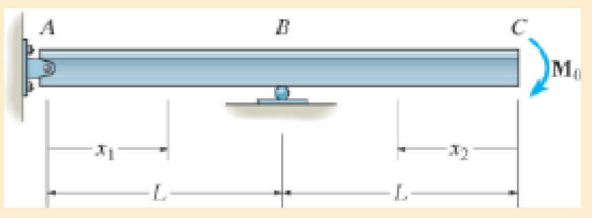
Chapter 12.2, Problem 12.23P
Determine the equations of the elastic curve using the coordinates x1 and x2 What is the deflection and slope at C? El is constant.
Prob. 12–23
Expert Solution & Answer
Want to see the full answer?
Check out a sample textbook solution
Students have asked these similar questions
1 of 2
Monthly Exam.
Automobile Eng. Dert
2nd Semster/3rd class
Max. Mark: 100%
Q1/A/ Compare between the long and short journal bearings
B/ With the help of Stribeck's curve, discuss different regimes of lubrication.
C/ Explain the importance of Tribology in the design of different machine elements
Q2 /A/ According to the SAE viscosity grading system all engine oils are divided into two
classes: monograde and multi-grade. Compare between them?
B/What are the differences between grease and Synthetic oils
C/ Explain the effect of eccentricity ratio & with respect to hydrodynamic journal bearing.
Q3/A/ What are the major factors which affect the selection of lubricants?
B/What are the criteria to classify sliding bearings?
C/ Answer of the following:
1. According to the SAE viscosity classification, the oil (SAE 40) is lower viscosity than the
oil (SAE 20) at the same temperature. (True or False)
2. For a slow speed-highly loaded bearing, used oils of high viscosity; while for high-speed…
The uniform rods have a mass per unit length of 10kg/m
. (Figure 1)If the dashpot has a damping coefficient of c=50N⋅s/m
, and the spring has a stiffness of k=600N/m
, show that the system is underdamped, and then find the pendulum's period of oscillation.
10-50.
The principal plane stresses and associated strains in a plane
at a point are σ₁ = 30 ksi, σ₂ = -10 ksi, e₁ = 1.14(10-3),
€2=-0.655(103). Determine the modulus of elasticity and
Poisson's ratio.
emps to plum...
Wednesday
FI
a
וח
2
Q Search
48 F5
- F6
4+
F7
FB
F9
FIO
FII
F12
&
*
S
6
7
8
9
ㅁ
F2
#
*F3
3
$
4
F4
%
W
E
R
T
Y
ப
S
ALT
D
F
G
H
X
C
V
B
N
J
Σ
H
L
ว
{
P
[
]
ALT
"
DELETE
BACKSPACE
NUM
LOCK
T
7
HOME
ENTER
4
PAUSE
SHIFT
CTRL
E
Chapter 12 Solutions
MECHANICS OF MATERIALS
Ch. 12.2 - In each case, determine the internal bending...Ch. 12.2 - Determine the slope and deflection of end A of the...Ch. 12.2 - Determine the slope and deflection of end A of the...Ch. 12.2 - Determine the slope of end A of the cantilevered...Ch. 12.2 - Determine the maximum deflection of the simply...Ch. 12.2 - Determine the maximum deflection of the simply...Ch. 12.2 - Determine the slope of the simply supported beam...Ch. 12.2 - An L2 steel strap having a thickness of 0.125 in....Ch. 12.2 - The L2 steel blade of the band saw wraps around...Ch. 12.2 - A picture is taken of a man performing a pole...
Ch. 12.2 - El is constant. Prob. 124Ch. 12.2 - Determine the deflection of end C of the...Ch. 12.2 - Determine the elastic curve for the cantilevered...Ch. 12.2 - The A-36 steel beam has a depth of 10 in. and is...Ch. 12.2 - Determine the equations of the elastic curve using...Ch. 12.2 - Determine the equations of the elastic curve for...Ch. 12.2 - Determine the equations of the elastic curve using...Ch. 12.2 - Determine the equations of the elastic curve using...Ch. 12.2 - Draw the bending-moment diagram for the shaft and...Ch. 12.2 - Determine the maximum deflection of the beam and...Ch. 12.2 - The simply supported shaft has a moment of inertia...Ch. 12.2 - A torque wrench is used to tighten the nut on a...Ch. 12.2 - The pipe can be assumed roller supported at its...Ch. 12.2 - Determine the equations of the elastic curve for...Ch. 12.2 - The bar is supported by a roller constraint at B,...Ch. 12.2 - Determine the deflection at B of the bar in Prob....Ch. 12.2 - Determine the equations of the elastic curve using...Ch. 12.2 - Determine the maximum deflection of the solid...Ch. 12.2 - Determine the elastic curve for the cantilevered...Ch. 12.2 - Determine the equations of the elastic curve using...Ch. 12.2 - Determine the equations of the elastic curve using...Ch. 12.2 - The floor beam of the airplane is subjected to the...Ch. 12.2 - Determine the maximum deflection of the simply...Ch. 12.2 - The beam is made of a material having a specific...Ch. 12.2 - Determine the slope at end B and the maximum...Ch. 12.2 - Determine the equation of the elastic curve using...Ch. 12.2 - Determine the equations of the elastic curve using...Ch. 12.3 - The shaft is supported at A by a journal bearing...Ch. 12.3 - The shaft supports the two pulley loads shown....Ch. 12.3 - The beam is made of a ceramic material. If it is...Ch. 12.3 - Determine the equation of the elastic curve, the...Ch. 12.3 - The beam is subjected to the load shown. Determine...Ch. 12.3 - Determine the equation of the elastic curve, the...Ch. 12.3 - Determine the equation of the elastic curve and...Ch. 12.3 - The shaft supports the two pulley loads. Determine...Ch. 12.3 - Determine the maximum deflection of the...Ch. 12.3 - Determine the slope at A and the deflection of end...Ch. 12.3 - Determine the maximum deflection in region AB of...Ch. 12.3 - Prob. 12.42PCh. 12.3 - Prob. 12.43PCh. 12.3 - Prob. 12.44PCh. 12.3 - Prob. 12.45PCh. 12.3 - Prob. 12.46PCh. 12.3 - Prob. 12.47PCh. 12.3 - Determine the value of a so that the displacement...Ch. 12.3 - Determine the displacement at C and the slope at...Ch. 12.3 - Determine the equations of the slope and elastic...Ch. 12.4 - Determine the slope and deflection of end A of the...Ch. 12.4 - Determine the slope and deflection of end A of the...Ch. 12.4 - Determine the slope and deflection of end A of the...Ch. 12.4 - Determine the slope and deflection at A of the...Ch. 12.4 - Prob. 12.11FPCh. 12.4 - Determine the maximum deflection of the simply...Ch. 12.4 - Determine the slope and deflection at C. El is...Ch. 12.4 - Determine the slope and deflection at C. El is...Ch. 12.4 - Determine the deflection of end B of the...Ch. 12.4 - Prob. 12.54PCh. 12.4 - The composite simply supported steel shaft is...Ch. 12.4 - Prob. 12.56PCh. 12.4 - Prob. 12.57PCh. 12.4 - Determine the deflection at C and the slope of the...Ch. 12.4 - Determine the maximum deflection of the...Ch. 12.4 - Prob. 12.60PCh. 12.4 - Determine the position a of the roller support B...Ch. 12.4 - Prob. 12.62PCh. 12.4 - Determine the slope and the deflection of end B of...Ch. 12.4 - The two A-36 steel bars have a thickness of 1 in....Ch. 12.4 - Determine the slope at A and the displacement at...Ch. 12.4 - Determine the deflection at C and the slopes at...Ch. 12.4 - Determine the maximum deflection within region AB....Ch. 12.4 - Determine the slope at A and the maximum...Ch. 12.4 - Determine the slope at C and the deflection at B....Ch. 12.4 - Determine the slope at A and the maximum...Ch. 12.4 - Determine the displacement of the 20-mm-diameter...Ch. 12.4 - The two force components act on the tire of the...Ch. 12.4 - Prob. 12.73PCh. 12.4 - The rod is constructed from two shafts for which...Ch. 12.4 - Prob. 12.75PCh. 12.4 - Determine the slope at point A and the maximum...Ch. 12.4 - Determine the position a of roller support B in...Ch. 12.4 - Determine the slope at B and deflection at C. El...Ch. 12.4 - Prob. 12.79PCh. 12.4 - Prob. 12.80PCh. 12.4 - Prob. 12.81PCh. 12.4 - Determine the maximum deflection of the beam. El...Ch. 12.5 - The W10 15 cantilevered beam is made of A-36...Ch. 12.5 - The W10 15 cantilevered beam is made of A-36...Ch. 12.5 - The W14 43 simply supported beam is made of A992...Ch. 12.5 - The W14 43 simply supported beam is made of A992...Ch. 12.5 - The W14 43 simply supported beam is made of A-36...Ch. 12.5 - The W14 43 simply supported beam is made of A-36...Ch. 12.5 - The W8 48 cantilevered beam is made of A-36 steel...Ch. 12.5 - The beam supports the loading shown. Code...Ch. 12.5 - The W24 104 A-36 steel beam is used to support...Ch. 12.5 - The W8 48 cantilevered beam is made of A-36 steel...Ch. 12.5 - The rod is pinned at its end A and attached to a...Ch. 12.5 - Prob. 12.94PCh. 12.5 - The pipe assembly consists of three equal-sized...Ch. 12.5 - The assembly consists of a cantilevered beam CS...Ch. 12.5 - Determine the smallest force F required to attract...Ch. 12.5 - Prob. 12.98PCh. 12.7 - Determine the reactions at the supports A and B,...Ch. 12.7 - Determine the reactions at the supports, then draw...Ch. 12.7 - Determine the reactions at the supports A, B, and...Ch. 12.7 - Determine the reactions at the supports A and B,...Ch. 12.7 - Determine the reactions at the supports A and B,...Ch. 12.7 - Determine the moment reactions at the supports A...Ch. 12.7 - Determine the reactions at the supports A and B,...Ch. 12.7 - Determine the reactions at the support A and B. EI...Ch. 12.7 - Determine the reactions at roller support A and...Ch. 12.7 - Determine the moment reactions at the supports A...Ch. 12.7 - The beam has a constant E1I1 and is supported by...Ch. 12.7 - The beam is supported by a pin at A, a roller at...Ch. 12.8 - Determine the moment reactions at the supports A...Ch. 12.8 - Determine the reaction at the supports, then draw...Ch. 12.8 - Determine the vertical reaction at the journal...Ch. 12.8 - Determine the reactions at the supports A and B,...Ch. 12.8 - Determine the reactions at the supports. EI is...Ch. 12.8 - Determine the vertical reaction at the journal...Ch. 12.9 - Determine the reactions at the fixed support A and...Ch. 12.9 - Determine the reactions at the fixed support A and...Ch. 12.9 - Determine the reactions at the fixed support A and...Ch. 12.9 - Determine the reaction at the roller B. EI is...Ch. 12.9 - Determine the reaction at the roller B. EI is...Ch. 12.9 - Determine the reaction at the roller support B if...Ch. 12.9 - Determine the reactions at the journal bearing...Ch. 12.9 - Determine the reactions at the supports, then draw...Ch. 12.9 - Determine the reactions at the supports, then draw...Ch. 12.9 - Determine the reactions at the supports A and B....Ch. 12.9 - The beam is used to support the 20-kip load....Ch. 12.9 - Determine the reactions at the supports A and B....Ch. 12.9 - Determine the reactions at the supports A and B....Ch. 12.9 - Before the uniform distributed load is applied to...Ch. 12.9 - The fixed supported beam AB is strengthened using...Ch. 12.9 - The beam has a constant E1I1, and is supported by...Ch. 12.9 - The beam is supported by the bolted supports at...Ch. 12.9 - Each of the two members is made from 6061-T6...Ch. 12.9 - The beam is made from a soft linear elastic...Ch. 12.9 - The beam AB has a moment of inertia I = 475 in4...Ch. 12.9 - The rim on the flywheel has a thickness t, width...Ch. 12.9 - Determine the moment developed in each corner....Ch. 12 - Determine the equation of the elastic curve. Use...Ch. 12 - Draw the bending-moment diagram for the shaft and...Ch. 12 - Determine the moment reactions at the supports A...Ch. 12 - Specify the slope at A and the maximum deflection....Ch. 12 - Determine the maximum deflection between the...Ch. 12 - Determine the slope at B and the deflection at C....Ch. 12 - Determine the reactions, then draw the shear and...Ch. 12 - El is constant.Ch. 12 - Using the method of superposition, determine the...
Additional Engineering Textbook Solutions
Find more solutions based on key concepts
Why is the study of database technology important?
Database Concepts (8th Edition)
How is the hydrodynamic entry length defined for flow in a pipe? Is the entry length longer in laminar or turbu...
Fluid Mechanics: Fundamentals and Applications
1.2 Explain the difference between geodetic and plane
surveys,
Elementary Surveying: An Introduction To Geomatics (15th Edition)
What is an uninitialized variable?
Starting Out with Programming Logic and Design (5th Edition) (What's New in Computer Science)
A byte is made up of eight a. CPUs b. addresses c. variables d. bits
Starting Out with Java: From Control Structures through Objects (7th Edition) (What's New in Computer Science)
What types of coolant are used in vehicles?
Automotive Technology: Principles, Diagnosis, And Service (6th Edition) (halderman Automotive Series)
Knowledge Booster


Learn more about
Need a deep-dive on the concept behind this application? Look no further. Learn more about this topic, mechanical-engineering and related others by exploring similar questions and additional content below.Similar questions
- 10−9. The state of strain at the point has components of ϵx = −100(10−6), ϵy = −200(10−6), and γxy=100(10−6). Use the strain transformation equations to determine (a) the in-plane principal strains and (b) the maximum in-plane shear strain and average normal strain. In each case specify the orientation of the element and show how the strains deform the element within the x−y plane.arrow_forwardThe strain gage is placed on the surface of the steel boiler as shown. If it is 0.5 in. long, determine the pressure in the boiler when the gage elongates 0.2(10−3) in. The boiler has a thickness of 0.5 in. and inner diameter of 60 in. Also, determine the maximum x, y in-plane shear strain in the material. Take Est=29(103)ksi, vst=0.3.arrow_forward(read image, answer given)arrow_forward
- 6/86 The connecting rod AB of a certain internal-combustion engine weighs 1.2 lb with mass center at G and has a radius of gyration about G of 1.12 in. The piston and piston pin A together weigh 1.80 lb. The engine is running at a constant speed of 3000 rev/min, so that the angular velocity of the crank is 3000(2)/60 = 100л rad/sec. Neglect the weights of the components and the force exerted by the gas in the cylinder compared with the dynamic forces generated and calculate the magnitude of the force on the piston pin A for the crank angle 0 = 90°. (Suggestion: Use the alternative moment relation, Eq. 6/3, with B as the moment center.) Answer A = 347 lb 3" 1.3" B 1.7" PROBLEM 6/86arrow_forward6/85 In a study of head injury against the instrument panel of a car during sudden or crash stops where lap belts without shoulder straps or airbags are used, the segmented human model shown in the figure is analyzed. The hip joint O is assumed to remain fixed relative to the car, and the torso above the hip is treated as a rigid body of mass m freely pivoted at O. The center of mass of the torso is at G with the initial position of OG taken as vertical. The radius of gyration of the torso about O is ko. If the car is brought to a sudden stop with a constant deceleration a, determine the speed v relative to the car with which the model's head strikes the instrument panel. Substitute the values m = 50 kg, 7 = 450 mm, r = 800 mm, ko = 550 mm, 0 = 45°, and a = 10g and compute v. Answer v = 11.73 m/s PROBLEM 6/85arrow_forwardUsing AutoCADarrow_forward
- 340 lb 340 lb Δarrow_forward4. In a table of vector differential operators, look up the expressions for V x V in a cylindrical coordinate system. (a) Compute the vorticity for the flow in a round tube where the velocity profile is = vo [1-(³] V₂ = Vo (b) Compute the vorticity for an ideal vortex where the velocity is Ve= r where constant. 2πг (c) Compute the vorticity in the vortex flow given by Ve= r 2лг 1- exp ( r² 4vt (d) Sketch all the velocity and vorticity profiles.arrow_forwardIn the figure, Neglects the heat loss and kinetic and potential energy changes, calculate the work produced by the turbine in kJ T = ??? Steam at P=3 MPa, T = 280°C Turbine Rigid tank V = 1000 m³ Turbine Rigid tank V = 100 m³ V = 1000 m³ V = 100 m³ The valve is opened. Initially: evacuated (empty) tank O a. 802.8 Initially: Closed valve O b. 572 O c. 159.93 Od. 415 e. 627.76 equilibriumarrow_forward
- Please find the torsional yield strength, the yield strength, the spring index, and the mean diameter. Use: E = 28.6 Mpsi, G = 11.5 Mpsi, A = 140 kpsi·in, m = 0.190, and relative cost= 1.arrow_forwardA viscoelastic column is made of a material with a creep compliance of D(t)= 0.75+0.5log10t+0.18(log10t)^2 GPA^-1 for t in s. If a constant compressive stress of σ0 = –100 MPa is applied at t = 0, how long will it take (= t1/2) for the height of the column to decrease to ½ its original value? Note: You will obtain multiple answers for this problem! One makes sense physically and one does not.arrow_forwardA group of 23 power transistors, dissipating 2 W each, are to be cooled by attaching them to a black-anodized square aluminum plate and mounting the plate on the wall of a room at 30°C. The emissivity of the transistor and the plate surfaces is 0.9. Assuming the heat transfer from the back side of the plate to be negligible and the temperature of the surrounding surfaces to be the same as the air temperature of the room, determine the length of the square plate if the average surface temperature of the plate is not to exceed 50°C. Start the iteration process with an initial guess of the size of the plate as 43 cm. The properties of air at 1 atm and the film temperature of (Ts + T)/2 = (50 + 30)/2 = 40°C are k = 0.02662 W/m·°C, ν = 1.702 × 10⁻⁵ m2 /s, Pr = 0.7255, and β = 0.003195 K–1. Multiple Choice 0.473 m 0.284 m 0.513 m 0.671 marrow_forward
arrow_back_ios
SEE MORE QUESTIONS
arrow_forward_ios
Recommended textbooks for you
 Elements Of ElectromagneticsMechanical EngineeringISBN:9780190698614Author:Sadiku, Matthew N. O.Publisher:Oxford University Press
 Mechanics of Materials (10th Edition)Mechanical EngineeringISBN:9780134319650Author:Russell C. HibbelerPublisher:PEARSON
 Thermodynamics: An Engineering ApproachMechanical EngineeringISBN:9781259822674Author:Yunus A. Cengel Dr., Michael A. BolesPublisher:McGraw-Hill Education
 Control Systems EngineeringMechanical EngineeringISBN:9781118170519Author:Norman S. NisePublisher:WILEY
 Mechanics of Materials (MindTap Course List)Mechanical EngineeringISBN:9781337093347Author:Barry J. Goodno, James M. GerePublisher:Cengage Learning
 Engineering Mechanics: StaticsMechanical EngineeringISBN:9781118807330Author:James L. Meriam, L. G. Kraige, J. N. BoltonPublisher:WILEY
Elements Of Electromagnetics
Mechanical Engineering
ISBN:9780190698614
Author:Sadiku, Matthew N. O.
Publisher:Oxford University Press
Mechanics of Materials (10th Edition)
Mechanical Engineering
ISBN:9780134319650
Author:Russell C. Hibbeler
Publisher:PEARSON
Thermodynamics: An Engineering Approach
Mechanical Engineering
ISBN:9781259822674
Author:Yunus A. Cengel Dr., Michael A. Boles
Publisher:McGraw-Hill Education
Control Systems Engineering
Mechanical Engineering
ISBN:9781118170519
Author:Norman S. Nise
Publisher:WILEY
Mechanics of Materials (MindTap Course List)
Mechanical Engineering
ISBN:9781337093347
Author:Barry J. Goodno, James M. Gere
Publisher:Cengage Learning
Engineering Mechanics: Statics
Mechanical Engineering
ISBN:9781118807330
Author:James L. Meriam, L. G. Kraige, J. N. Bolton
Publisher:WILEY
Solids: Lesson 53 - Slope and Deflection of Beams Intro; Author: Jeff Hanson;https://www.youtube.com/watch?v=I7lTq68JRmY;License: Standard YouTube License, CC-BY