Concept explainers
Videos
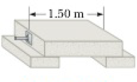
The lintel of prestressed reinforced concrete in Figure P12.27 is 1.50 m long. The concrete encloses one steel reinforcing rod with cross-sectional area 1.50 cm2. The rod joins two strong end plates. The cross-sectional area of the concrete perpendicular to the rod is 50.0 cm2. Young’s modulus for the concrete is 30.0 × 10⁹ N/m2. After the concrete cures and the original tension T1 in the rod is released, the concrete is to be under compressive stress 8.00 × 10⁶ N/m2. (a) By what distance will the rod compress the concrete when the original tension in the rod is released? (b) What is the new tension T2 in the rod? (c) The rod will then be how much longer than its unstressed length? (d) When the concrete was poured, the rod should have been stretched by what extension distance from its unstressed length? (e) Find the required original tension T1 in the rod.
Figure P12.27
(a)
The compressed length of the rod when the original tension in the rod is released.
Answer to Problem 27AP
The compressed length of the rod when the original tension in the rod is released is
Explanation of Solution
The length of the concrete is
Formula to calculate the compressive strain is,
Here,
Formula to calculate the modulus of rigidity of the concrete is,
Substitute
Substitute
Conclusion:
Therefore, the compressed length of the rod when the original tension in the rod is released is
(b)
The magnitude of the new tension in the rod.
Answer to Problem 27AP
The magnitude of the new tension in the rod is
Explanation of Solution
Formula to calculate the compressive stress is,
Here,
Substitute
Conclusion:
Therefore, the magnitude of the new tension in the rod is
(c)
The increase in length of the rod due to tension.
Answer to Problem 27AP
The increase in length of the rod due to tension is
Explanation of Solution
Formula to calculate the tensile stress on the rod is,
Here,
Formula to calculate the tensile strain is,
Here,
Formula to calculate Young’s modulus is,
Substitute
Substitute
Conclusion:
Therefore, the increase in length of the rod due to tension is
(d)
The required extension of the rod while concrete was poured.
Answer to Problem 27AP
The required extension of the rod while concrete was poured is
Explanation of Solution
The length of the concrete is
Formula to calculate the required extension length of the concrete is,
Substitute
Conclusion:
Therefore, the required extension of the rod while concrete was poured is
(e)
The required original tension on the rod.
Answer to Problem 27AP
The required original tension on the rod is
Explanation of Solution
Formula to calculate the stress due to original tension is,
Here,
Formula to calculate the tensile strain is,
Formula to calculate Young’s modulus of the steel rod is,
Here,
Substitute
`
Substitute
Conclusion:
Therefore, the required original tension on the rod is
Want to see more full solutions like this?
Chapter 12 Solutions
Physics:f/sci.+engrs.,ap Ed.


 Physics for Scientists and Engineers: Foundations...PhysicsISBN:9781133939146Author:Katz, Debora M.Publisher:Cengage Learning
 Physics for Scientists and EngineersPhysicsISBN:9781337553278Author:Raymond A. Serway, John W. JewettPublisher:Cengage Learning
 Physics for Scientists and Engineers with Modern ...PhysicsISBN:9781337553292Author:Raymond A. Serway, John W. JewettPublisher:Cengage Learning
 Physics for Scientists and Engineers, Technology ...PhysicsISBN:9781305116399Author:Raymond A. Serway, John W. JewettPublisher:Cengage Learning
 University Physics Volume 1PhysicsISBN:9781938168277Author:William Moebs, Samuel J. Ling, Jeff SannyPublisher:OpenStax - Rice University
 College PhysicsPhysicsISBN:9781938168000Author:Paul Peter Urone, Roger HinrichsPublisher:OpenStax College