
Videos
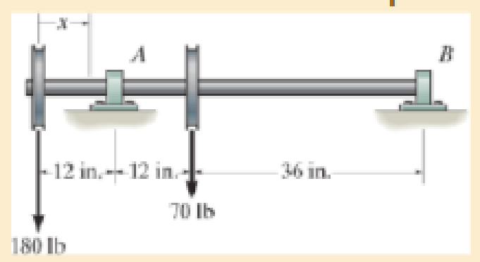
Determine the equation of the elastic curve. Use discontinuity functions EI is constant.
Answer to Problem 1RP
The Equation of the elastic curve is,
Explanation of Solution
Given information:
The length of the beam is 60 in..
EI is constant.
Calculation:
Sketch the Free Body Diagram of the beam as shown in Figure 1.
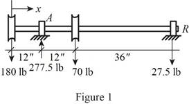
Refer to Figure 1.
Find the support reaction as shown below.
Apply the Equations of Equilibrium as shown below.
Take moment about A is Equal to zero.
Summation of forces along vertical direction is Equal to zero.
Consider the x distance from left support.
Take moment about the section as shown below.
Apply the slope and elastic curve as shown below.
Here, EI is the flexural rigidity,
Substitute
Integrate both sides of the Equation.
Integrate both sides of the Equation (2).
Apply the boundary conditions as shown below.
- i. The value of
- ii. The value of
Apply boundary condition (i) in Equation (3).
Substitute 0 for
Apply boundary condition (ii) in Equation (3).
Substitute 0 for
Solving Equations (4) and (5) we get,
Substitute
Therefore, the Equation of the elastic curve is,
Want to see more full solutions like this?
Chapter 12 Solutions
Mechanics of Materials
Additional Engineering Textbook Solutions
Starting Out with Programming Logic and Design (5th Edition) (What's New in Computer Science)
Starting Out with Python (4th Edition)
Introduction To Programming Using Visual Basic (11th Edition)
Computer Science: An Overview (13th Edition) (What's New in Computer Science)
Java: An Introduction to Problem Solving and Programming (8th Edition)


- The 120 kg wheel has a radius of gyration of 0.7 m. A force P with a magnitude of 50 N is applied at the edge of the wheel as seen in the diagram. The coefficient of static friction is 0.3, and the coefficient of kinetic friction is 0.25. Find the acceleration and angular acceleration of the wheel.arrow_forwardAuto Controls Using MATLAB , find the magnitude and phase plot of the compensators NO COPIED SOLUTIONSarrow_forward4-81 The corner shown in Figure P4-81 is initially uniform at 300°C and then suddenly exposed to a convection environment at 50°C with h 60 W/m². °C. Assume the = 2 solid has the properties of fireclay brick. Examine nodes 1, 2, 3, 4, and 5 and deter- mine the maximum time increment which may be used for a transient numerical calculation. Figure P4-81 1 2 3 4 1 cm 5 6 1 cm 2 cm h, T + 2 cmarrow_forward
- Auto Controls A union feedback control system has the following open loop transfer function where k>0 is a variable proportional gain i. for K = 1 , derive the exact magnitude and phase expressions of G(jw). ii) for K = 1 , identify the gaincross-over frequency (Wgc) [where IG(jo))| 1] and phase cross-overfrequency [where <G(jw) = - 180]. You can use MATLAB command "margin" to obtain there quantities. iii) Calculate gain margin (in dB) and phase margin (in degrees) ·State whether the closed-loop is stable for K = 1 and briefly justify your answer based on the margin . (Gain marginPhase margin) iv. what happens to the gain margin and Phase margin when you increase the value of K?you You can use for loop in MATLAB to check that.Helpful matlab commands : if, bode, margin, rlocus NO COPIED SOLUTIONSarrow_forwardAuto Controls Hand sketch the root Focus of the following transfer function How many asymptotes are there ?what are the angles of the asymptotes?Does the system remain stable for all values of K NO COPIED SOLUTIONSarrow_forward-400" 150" in Datum 80" 90" -280"arrow_forward
- 7) Please draw the front, top and side view for the following object. Please cross this line outarrow_forwardA 10-kg box is pulled along P,Na rough surface by a force P, as shown in thefigure. The pulling force linearly increaseswith time, while the particle is motionless att = 0s untilit reaches a maximum force of100 Nattimet = 4s. If the ground has staticand kinetic friction coefficients of u, = 0.6 andHU, = 0.4 respectively, determine the velocityof the A 1 0 - kg box is pulled along P , N a rough surface by a force P , as shown in the figure. The pulling force linearly increases with time, while the particle is motionless at t = 0 s untilit reaches a maximum force of 1 0 0 Nattimet = 4 s . If the ground has static and kinetic friction coefficients of u , = 0 . 6 and HU , = 0 . 4 respectively, determine the velocity of the particle att = 4 s .arrow_forwardCalculate the speed of the driven member with the following conditions: Diameter of the motor pulley: 4 in Diameter of the driven pulley: 12 in Speed of the motor pulley: 1800 rpmarrow_forward
 Mechanics of Materials (MindTap Course List)Mechanical EngineeringISBN:9781337093347Author:Barry J. Goodno, James M. GerePublisher:Cengage Learning