
Videos
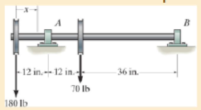
Determine the equation of the elastic curve. Use discontinuity functions EI is constant.
Answer to Problem 1RP
The Equation of the elastic curve is,
Explanation of Solution
Given information:
The length of the beam is 60 in..
EI is constant.
Calculation:
Sketch the Free Body Diagram of the beam as shown in Figure 1.
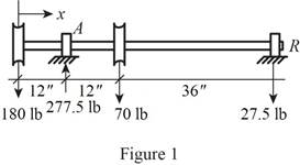
Refer to Figure 1.
Find the support reaction as shown below.
Apply the Equations of Equilibrium as shown below.
Take moment about A is Equal to zero.
Summation of forces along vertical direction is Equal to zero.
Consider the x distance from left support.
Take moment about the section as shown below.
Apply the slope and elastic curve as shown below.
Here, EI is the flexural rigidity,
Substitute
Integrate both sides of the Equation.
Integrate both sides of the Equation (2).
Apply the boundary conditions as shown below.
- i. The value of
- ii. The value of
Apply boundary condition (i) in Equation (3).
Substitute 0 for
Apply boundary condition (ii) in Equation (3).
Substitute 0 for
Solving Equations (4) and (5) we get,
Substitute
Therefore, the Equation of the elastic curve is,
Want to see more full solutions like this?
Chapter 12 Solutions
MECHANICS OF MATERIALS
Additional Engineering Textbook Solutions
Starting Out with Programming Logic and Design (5th Edition) (What's New in Computer Science)
Starting Out with Python (4th Edition)
Introduction To Programming Using Visual Basic (11th Edition)
Computer Science: An Overview (13th Edition) (What's New in Computer Science)
Java: An Introduction to Problem Solving and Programming (8th Edition)


- 2. Figure below shows a U-tube manometer open at both ends and containing a column of liquid mercury of length l and specific weight y. Considering a small displacement x of the manometer meniscus from its equilibrium position (or datum), determine the equivalent spring constant associated with the restoring force. Datum Area, Aarrow_forward1. The consequences of a head-on collision of two automobiles can be studied by considering the impact of the automobile on a barrier, as shown in figure below. Construct a mathematical model (i.e., draw the diagram) by considering the masses of the automobile body, engine, transmission, and suspension and the elasticity of the bumpers, radiator, sheet metal body, driveline, and engine mounts.arrow_forward3.) 15.40 – Collar B moves up at constant velocity vB = 1.5 m/s. Rod AB has length = 1.2 m. The incline is at angle = 25°. Compute an expression for the angular velocity of rod AB, ė and the velocity of end A of the rod (✓✓) as a function of v₂,1,0,0. Then compute numerical answers for ȧ & y_ with 0 = 50°.arrow_forward
- 2.) 15.12 The assembly shown consists of the straight rod ABC which passes through and is welded to the grectangular plate DEFH. The assembly rotates about the axis AC with a constant angular velocity of 9 rad/s. Knowing that the motion when viewed from C is counterclockwise, determine the velocity and acceleration of corner F.arrow_forward500 Q3: The attachment shown in Fig.3 is made of 1040 HR. The static force is 30 kN. Specify the weldment (give the pattern, electrode number, type of weld, length of weld, and leg size). Fig. 3 All dimension in mm 30 kN 100 (10 Marks)arrow_forward(read image) (answer given)arrow_forward
- A cylinder and a disk are used as pulleys, as shown in the figure. Using the data given in the figure, if a body of mass m = 3 kg is released from rest after falling a height h 1.5 m, find: a) The velocity of the body. b) The angular velocity of the disk. c) The number of revolutions the cylinder has made. T₁ F Rd = 0.2 m md = 2 kg T T₂1 Rc = 0.4 m mc = 5 kg ☐ m = 3 kgarrow_forward(read image) (answer given)arrow_forward11-5. Compute all the dimensional changes for the steel bar when subjected to the loads shown. The proportional limit of the steel is 230 MPa. 265 kN 100 mm 600 kN 25 mm thickness X Z 600 kN 450 mm E=207×103 MPa; μ= 0.25 265 kNarrow_forward
- T₁ F Rd = 0.2 m md = 2 kg T₂ Tz1 Rc = 0.4 m mc = 5 kg m = 3 kgarrow_forward2. Find a basis of solutions by the Frobenius method. Try to identify the series as expansions of known functions. (x + 2)²y" + (x + 2)y' - y = 0 ; Hint: Let: z = x+2arrow_forward1. Find a power series solution in powers of x. y" - y' + x²y = 0arrow_forward
 Mechanics of Materials (MindTap Course List)Mechanical EngineeringISBN:9781337093347Author:Barry J. Goodno, James M. GerePublisher:Cengage Learning