Draw the shear and bending moment diagrams for the girders of given frame.
Explanation of Solution
Given information:
The uniformly distributed load acting along the girder DEF (w) is 30 kN/m.
The horizontal distance of the point AB and BC
The vertical distance of the members AD, BE, and CF
Calculation:
The span length and loads for the two girders of the frame DE and EF are same; therefore the approximate shear and bending moment diagrams for the girders will also be the same.
Consider the girder DE.
Determine the span for the middle portion of the girder using the relation.
Substitute 6 m for L.
Determine the span for the two end portion of the girder using the relation.
Substitute 6 m for L.
Draw the statically determinate girder portion as in Figure (1).
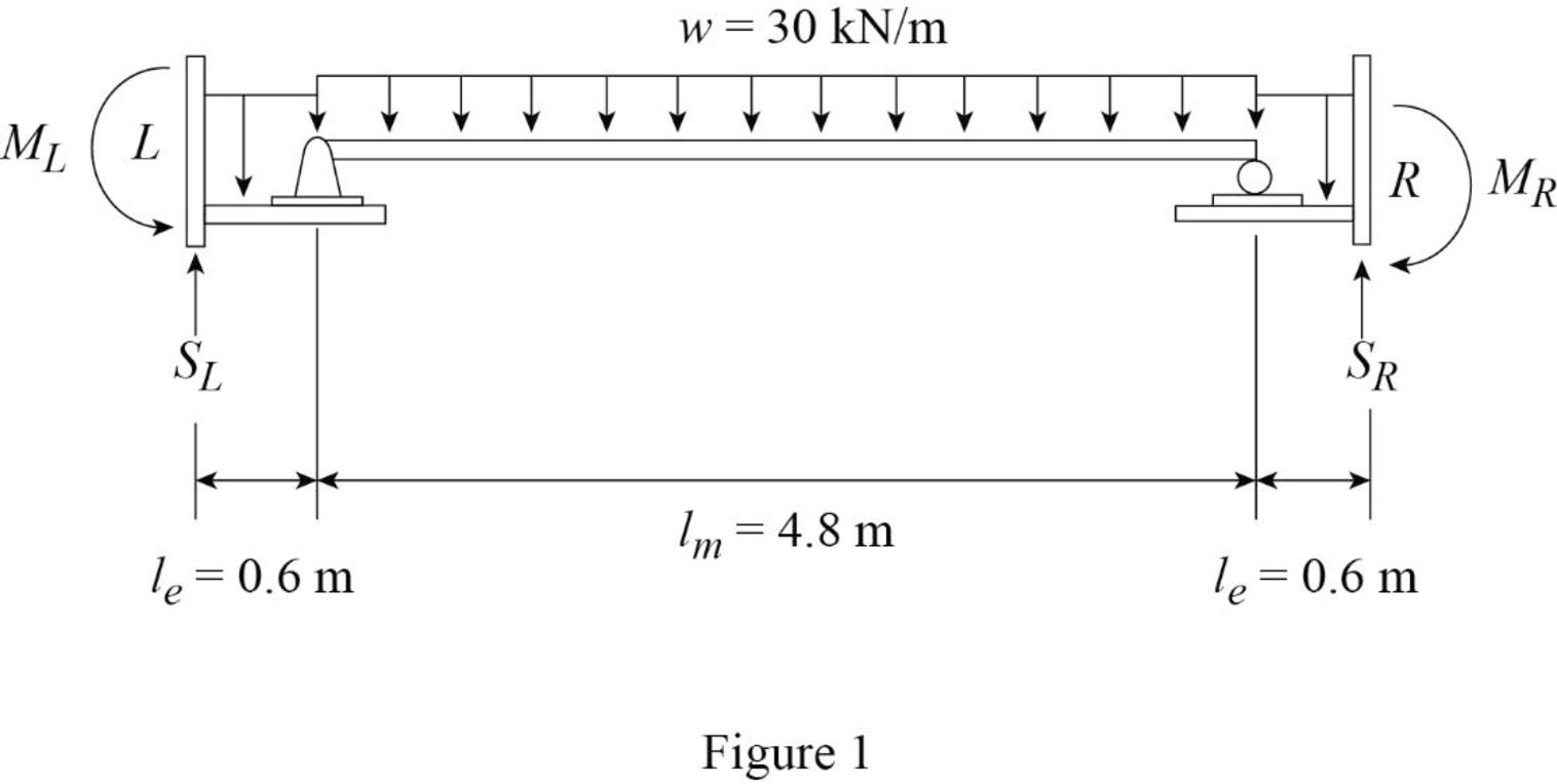
Consider the equilibrium of the simply supported middle portion of the girder.
Determine the vertical reactions at the end portion using the relation.
Substitute 30 kN/m for w and 4.8 m for
Consider the equilibrium conditions of the end portions of the girder.
Consider upward direction is positive and counter clockwise moment is positive.
Determine the support reaction at the left end.
Apply the equations of equilibrium to the left end portion.
Substitute 30 kN/m for w, 0.6 m for
Determine the moment at the left end.
Take moment about left end is equal to zero.
Substitute 30 kN/m for w, 0.6 m for
Consider upward direction is positive and clockwise moment is positive.
Determine the support reaction at the right end.
Apply the equations of equilibrium to the right end portion.
Substitute 30 kN/m for w, 0.6 m for
Determine the moment at the right end.
Take moment about right end is equal to zero.
Substitute 30 kN/m for w, 0.6 m for
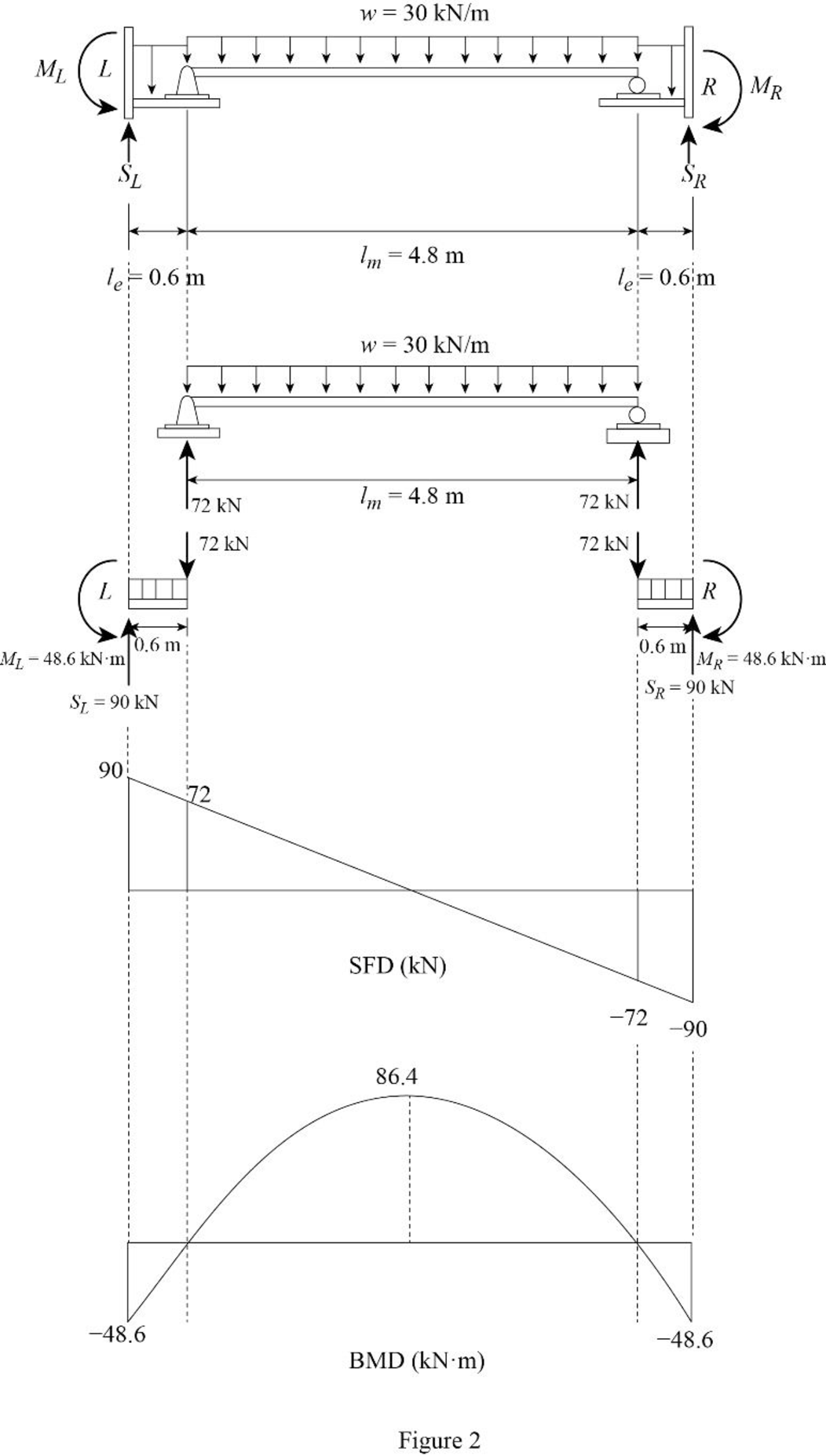
Determine the maximum bending moment at the middle of the girder using the relation.
Substitute 30 kN/m for w and 4.8 m for
Draw the shear force and bending moment diagram as in Figure (2).
Want to see more full solutions like this?
Chapter 12 Solutions
Structural Analysis, Si Edition

- B2. For the truss below, determine all member forces. Hint: see the provided slide with the problem set. P₁ = 12 kip and P₂ = 6 kip (20 pts). P₁ 16 ft D 8 ft 8 ft 8 ft B K E 8 ft 8 ft 8 ft H 8 ft В G 1000 8 ftarrow_forward14.1 A beam of rectangular cross section is 125 mm wide and 200 mm deep. If the maximum bending moment is 28.5 kN⚫m, determine (a) the maximum tensile and compressive bending stress, and (b) the bending stress 25 mm from the top of the section. 14.2 A rectangular beam 50 mm wide and 100 mm deep is subjected to bending. What bending moment will cause a maximum bending stress of 137.9 MN/m² (MPa)? 14.3 Determine the bending moment in a rectangular beam 3 in. wide and 6 in. deep if the maximum bend- ing stress is 15,000 psi.arrow_forwardB3. For the Howe truss below, assume all members are pin connected and take P₁ = 5 kN and P₂ = 10 kN: a. Determine all member forces (16 pts). b. Use a section cut to verify your answers for members GF, GD, and CD (4 Pts) P₁ A H 500 8 0000 B 0000] 2 m m 2 m 3 m B E D marrow_forward
- I need detailed help solving this exercise from homework of Engineering Mathematics II.I do not really understand how to do, please do it step by step, not that long but clear. Thank you!P.S.: Please do not use AI, thanks!arrow_forwardI need detailed help solving this exercise from homework of Engineering Mathematics II.I do not really understand how to do, please do it step by step, not that long but clear. Thank you!P.S.: Please do not use AI, thanks!arrow_forwardI need detailed help solving this exercise from homework of Engineering Mathematics II.I do not really understand how to do, please do it step by step, not that long but clear. Thank you!P.S.: Please do not use AI, thanks!arrow_forward
- I need detailed help solving this exercise from homework of Engineering Mathematics II.I do not really understand how to do, please do it step by step, not that long but clear. Thank you!P.S.: Please do not use AI, thanks!arrow_forwardI need detailed help solving this exercise from homework of Engineering Mathematics II.I do not really understand how to do, please do it step by step, not that long but clear. Thank you!P.S.: Please do not use AI, thanks!arrow_forwardI need detailed help solving this exercise from homework of Engineering Mathematics II.I do not really understand how to do, please do it step by step, not that long but clear. Thank you!P.S.: Please do not use AI, thanks!arrow_forward
- I need detailed help solving this exercise from homework of Engineering Mathematics II.I do not really understand how to do, please do it step by step, not that long but clear. Thank you!P.S.: Please do not use AI, thanks!arrow_forwardI need detailed help solving this exercise from homework of Engineering Mathematics II.I do not really understand how to do, please do it step by step, not that long but clear. Thank you!P.S.: Please do not use AI, thanks!arrow_forwardB1.For the truss below, take P₁ = 4 kip and P₂ = 3 kip: a. Determine all member forces. Hint: first find zero-force members (16 pts). b. Use a section cut to verify your answers for members JI, BI, and BC (4 Pts) В 18 ft 6 ft H B 6 ft C 8 ft D p81 8 ft E 8 ft 6 ft F6ftarrow_forward
