
Videos
(a)
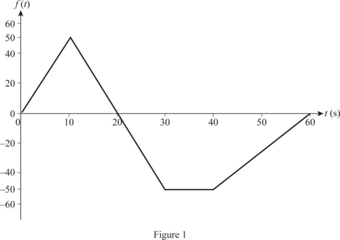
Plot the sketch of given function
(a)
Explanation of Solution
Given data:
Calculation:
Construct a single continuous definition for the function using step function as follows:
Use the values and draw the sketch of expression
Conclusion:
Thus, the sketch of given expression
(b)
Write the expression for the given function
(b)
Answer to Problem 1P
The expression for the given function
Explanation of Solution
Calculation:
Construct a single continuous definition for the function using step function as follows:
Use the values and write the expression for
Conclusion:
Thus, the expression for the given function
Want to see more full solutions like this?
Chapter 12 Solutions
EBK ELECTRIC CIRCUITS


- An 18.65 kW, 4-pole, 50 Hz, 3-phase induction motor has friction and windage losses of 2.5% of the output. The full-load slip is 4%. Find for full-load (i) the rotor cu loss (ii) the rotor input power (iii) the output torque.arrow_forwardQ1: Consider the finite state machine logic implementation in Fig. shown below: a. b. Construct the state diagram. Repeat the circuit design using j-k flip flop. C'lk A D 10 Clk Q D 32 Cik O 31 Please solve the question on a sheet of paper by hand and explain everything related to the question step by step.arrow_forwardAnot ined sove in peaper S PU +96 An 18.65 kW, 4-pole, 50 Hz, 3-phase induction motor has friction and windage losses of 2.5% of the output. The full-load slip is 4 %. Find for full-load (i) the rotor cu loss (ii) the rotor input power (iii) the output torque. 750 1 T el Marrow_forward
- Alternator has star-connected,4-pole, 50 Hz as the following data: Flux per pole-0.12 Wb; No. of slot/pole/phase=4; conductor/slot=4; Each coil spans 150° (electrical degree) pitches Find (i) number of turns per phase (ii) distribution factor (iii) pitch factor (iv) no-load phase voltage (v) no-load line voltage.arrow_forwardAlternator has star-connected,4-pole, 50 Hz as the following data: Flux per pole-0.12 Wb; No. of slot/pole/phase=4; conductor/slot=4; Each coil spans 150° (electrical degree) pitches Find (i) number of turns per phase (ii) distribution factor (iii) pitch factor (iv) no-load phase voltage (v) no-load line voltage.arrow_forwardA) Suppose you were desiging a circuit that required two LEDs for "power on" indication. The power supply voltage is 5 volts, and each LED is rated at 1.6 volts and 20 mA. Calculate the dropping resistor sizes and power ratings: B) After doing this, a co-worker looks at your circuit and suggests a modification. Why not use a single dropping resistor for both LEDs, economizing the number of components necessary? Re-calculate the dropping resistor ratings (resistance and power) for the new design. Include the total power consumed by the circuit and the power delivered by the source.arrow_forward
- S A L ined sove in peaper ۳/۱ 16852 Alternator has star-connected,4-pole, 50 Hz as the following data: Flux per pole-0.12 Wb; No. of slot/pole/phase-4; conductor/slot-4; Each coil spans 150° (electrical degree) pitches Find (i) number of turns per phase (ii) distribution factor (iii) pitch factor (iv) no-load phase voltage (v) no-load line voltage. 2ci25 750 r 2.01 ४arrow_forwardA) Complete the table of values for this circuit: B) Draw the schematic include polarityarrow_forward(choose R1, R2, R3, R4, R5 and assume that 300 β = , all resistors must be greater than zero) such that the following specifications are met: • Minimum open loop gain, Aol, 40dB (can be more, this is the minimum requirement) • Input current (at input terminals) <1uA • Power dissipation DC P ≤20mW • VCC=10V, VEE=0VI NEED HELP, I WANT ONLY TO CALCULATE THE RESISTORSarrow_forward
- 80 V 300 Ω t = 0 500 i(t) Vc(t) 40 nF 2,5 mH -arrow_forwardProblem 1: Two-Force Equilibrium A 12 kg traffic light is suspended by two cables attached to a ceiling. Determine the force in Cable 1 (AB) and Cable 2 (AC). In other words, determine the tension in each cable, assuming the system is in static equilibrium. Barrow_forwardIf the Z-axis changes, what is the effect A circularly polarized wave, traveling in the +z-direction, is received by an elliptically polarized antenna whose reception characteristics near the main lobe are given approx- imately by E₁ = (2â, + jâ] f(r. 8. d) Find the polarization loss factor PLF (dimensionless and in dB) when the incident wave is (a) right-hand (CW) (b) left-hand (CCW) An elliptically polarized wave traveling in the negative z-direction is received by a circularly polarized antenna. The vector describing the polarization of the incident wave is given by Ei= 2ax + jay .Find the polarization loss factor PLF (dimensionless and in dB) when the wave that would be transmitted by the antenna is (a) right-hand CP (b) left-hand CP.arrow_forward
 Introductory Circuit Analysis (13th Edition)Electrical EngineeringISBN:9780133923605Author:Robert L. BoylestadPublisher:PEARSON
 Delmar's Standard Textbook Of ElectricityElectrical EngineeringISBN:9781337900348Author:Stephen L. HermanPublisher:Cengage Learning
 Programmable Logic ControllersElectrical EngineeringISBN:9780073373843Author:Frank D. PetruzellaPublisher:McGraw-Hill Education
 Fundamentals of Electric CircuitsElectrical EngineeringISBN:9780078028229Author:Charles K Alexander, Matthew SadikuPublisher:McGraw-Hill Education
 Electric Circuits. (11th Edition)Electrical EngineeringISBN:9780134746968Author:James W. Nilsson, Susan RiedelPublisher:PEARSON
 Engineering ElectromagneticsElectrical EngineeringISBN:9780078028151Author:Hayt, William H. (william Hart), Jr, BUCK, John A.Publisher:Mcgraw-hill Education,