
Electrical Wiring Residential
19th Edition
ISBN: 9781337101837
Author: Ray C. Mullin, Phil Simmons
Publisher: Cengage Learning
expand_more
expand_more
format_list_bulleted
Concept explainers
Videos
Textbook Question
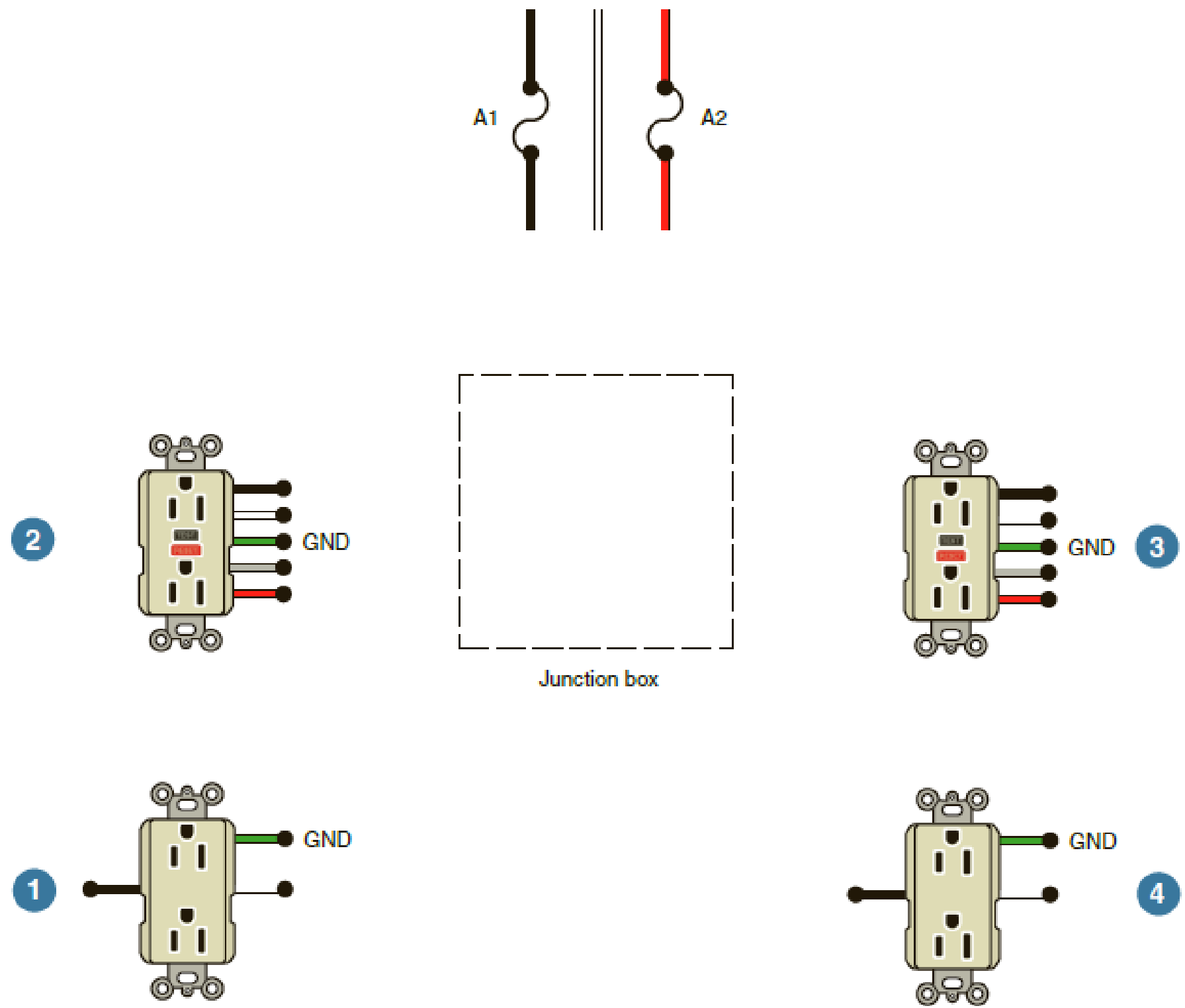
Chapter 12, Problem 16R
Complete the wiring diagram, connecting feed-through GFCI 2 to also protect receptacle 1, both to be supplied by Circuit A1. Connect feed-through GFCI 3 to also protect receptacle 4, both to be supplied by Circuit A2. Use colored pencils or markers to show proper color. Assume that the wiring method is EMT, where more freedom in the choice of insulation colors is possible.
Expert Solution & Answer

Trending nowThis is a popular solution!

Students have asked these similar questions
I need help checking if its correct
-E1 + VR1 + VR4 – E2 + VR3 = 0 -------> Loop 1 (a)
R1(I1) + R4(I1 – I2) + R3(I1) = E1 + E2 ------> Loop 1 (b)
R1(I1) + R4(I1) - R4(I2) + R3(I1) = E1 + E2 ------> Loop 1 (c)
(R1 + R3 + R4) (I1) - R4(I2) = E1 + E2 ------> Loop 1 (d)
Now that we have loop 1 equation will procced on finding the equation of I2 current loop. However, a reminder that because we are going in a clockwise direction, it goes against the direction of the current. As such we will get an equation for the matrix that will be:
E2 – VR4 – VR2 + E3 = 0 ------> Loop 2 (a)
-R4(I2 – I1) -R2(I2) = -E2 – E3 ------> Loop 2 (b)
-R4(I2) + R4(I1) - R2(I2) = -E2 – E3 -----> Loop 2 (c)
R4(I1) – (R4 + R2)(I2) = -E2 – E3 -----> Loop 2 (d)
These two equations will be implemented to the matrix formula I = inv(A) * b
R11 R12
(R1 + R3 + R4)
-R4
-R4
R4 + R2
10.2 For each of the following groups of sources, determineif the three sources constitute a balanced source, and if it is,determine if it has a positive or negative phase sequence.(a) va(t) = 169.7cos(377t +15◦) Vvb(t) = 169.7cos(377t −105◦) Vvc(t) = 169.7sin(377t −135◦) V(b) va(t) = 311cos(wt −12◦) Vvb(t) = 311cos(wt +108◦) Vvc(t) = 311cos(wt +228◦) V(c) V1 = 140 −140◦ VV2 = 114 −20◦ VV3 = 124 100◦ V
Apply single-phase equivalency to determine the linecurrents in the Y-D network shown in Fig. P10.13. The loadimpedances are Zab = Zbc = Zca = (25+ j5) W
Chapter 12 Solutions
Electrical Wiring Residential
Ch. 12 - If everything on Circuit B7 were turned on, what...Ch. 12 - From what panelboard does the kitchen lighting...Ch. 12 - How many luminaires are connected to the kitchen...Ch. 12 - What color fluorescent lamps are recommended for...Ch. 12 - a. What is the minimum number of 20-ampere...Ch. 12 - Prob. 6RCh. 12 - Prob. 7RCh. 12 - Duplex receptacles connected to the 20-ampere...Ch. 12 - Prob. 9RCh. 12 - A fundamental rule regarding the grounding of...
Ch. 12 - How many circuit conductors enter the box a. where...Ch. 12 - Prob. 12RCh. 12 - Where is the speed control for the range hood fan...Ch. 12 - Who is to furnish the range hood? _____Ch. 12 - Prob. 15RCh. 12 - Complete the wiring diagram, connecting...Ch. 12 - Each 20-ampere small-appliance branch-circuit load...Ch. 12 - a. The Code requires a minimum of two...Ch. 12 - According to 210.52, no point along the floor line...Ch. 12 - Prob. 21RCh. 12 - Electric fans produce a certain amount of noise....Ch. 12 - Prob. 23RCh. 12 - Prob. 24RCh. 12 - Prob. 25RCh. 12 - Prob. 26RCh. 12 - Prob. 27RCh. 12 - The following is a layout for the lighting circuit...
Knowledge Booster


Learn more about
Need a deep-dive on the concept behind this application? Look no further. Learn more about this topic, electrical-engineering and related others by exploring similar questions and additional content below.Similar questions
- 10.8 In the network of Fig. P10.8, Za = Zb = Zc = (25+ j5) W.Determine the line currents.arrow_forwardUsing D flip-flops, design a synchronous counter. The counter counts in the sequence 1,3,5,7, 1,7,5,3,1,3,5,7,.... when its enable input x is equal to 1; otherwise, the counter count 0. Present state Next state x=0 Next state x=1 Output SO 52 S1 1 S1 54 53 3 52 53 S2 56 51 0 $5 5 54 S4 53 0 55 58 57 7 56 56 55 0 57 S10 59 1 58 58 S7 0 59 S12 S11 7 $10 $10 59 0 $11 $14 $13 5 $12 S12 $11 0 513 $15 SO 3 S14 $14 S13 0 $15 515 SO 0 Explain how to get the table step by step with drawing the state diagram and finding the Karnaugh map.arrow_forwardFor the oscillator resonance circuit shown in Fig. (5), derive the oscillation frequency Feedback and open-loop gains. L₁ 5 mH (a) ell +10 V R₁ ww R3 S C2 HH 1 με 1000 pF 100 pF R₂ 1 με RA H (b) +9 V R4 CA 470 pF C₁ R3 HH 1 με R₁ ww L₁ 000 1.5 mH R₂ ww Hi 1 μF L2 m 10 mHarrow_forward
- Expert handwritten solution onlyarrow_forwardB. For the oscillator circuit shown in frequency, feedback and open-loop gains. +10 V name the circuit, derive and find the oscillation P.Av +9 V -000 4₁ 5 mH w R₁ C₂ HH 1 με w 100 pF R₂ T R CA www. 470 pF w ww www 1000 pF HH 1μF C₁ HH 1μF Ra ww HI 4₁ 000 1.5 mH H 4 AF 000 10 mHarrow_forwardI want to check if the current that I have from using the mesh analysis is correct? I1 = 0.214mA I2 = -0.429mAarrow_forward
- I want to find the current by using mesh analysis pleasearrow_forwardI want to find the current by using mesh analysis pleasearrow_forwardR₁ W +10 V R3 +9 V C₂ R₁ CA C₁ 470 pF HH 1000 pF HH 1 με C4 1 μF 1 uF C₁ R₂ R4 100 pF Find Open-loop Jain L₁ 5 mH (a) Av=S,B={" H R₁₂ ✓ ww (b) R₁ L₁ 000 1.5 mH R₂ H 1 uF 12 10 mHarrow_forward
- A) Calculate the efficiency of the test transformer at the resistive loads (X-25%, 50%, 75%, 100%, 125% full load). B) From part (A) draw the plot (efficiency Vs power output) of the transformer. C) Discuss the plot of part (B).arrow_forwarda- Determine fH; and Ho b- Find fg and fr. c- Sketch the frequency response for the high-frequency region using a Bode plot and determine the cutoff frequency. Ans: 277.89 KHz; 2.73 MHz; 895.56 KHz; 107.47 MHz. 14V Cw=5pF Cwo-8pF Coc-12 pF 5.6kQ Ch. 40. pF C-8pF 68kQ 0.47µF Vo 0.82 kQ V₁ B=120 0.47µF www 3.3kQ 10kQ 1.2kQ =20µF Narrow_forwardUsing D flip-flops, design a synchronous counter. The counter counts in the sequence 1,3,5,7, 1,7,5,3,1,3,5,7,.... when its enable input x is equal to 1; otherwise, the counter. This counter is for individual settings only need the state diagram and need the state table to use 16 states from So to S15.arrow_forward
arrow_back_ios
SEE MORE QUESTIONS
arrow_forward_ios
Recommended textbooks for you
 EBK ELECTRICAL WIRING RESIDENTIALElectrical EngineeringISBN:9781337516549Author:SimmonsPublisher:CENGAGE LEARNING - CONSIGNMENT
 Electricity for Refrigeration, Heating, and Air C...Mechanical EngineeringISBN:9781337399128Author:Russell E. SmithPublisher:Cengage Learning
EBK ELECTRICAL WIRING RESIDENTIAL
Electrical Engineering
ISBN:9781337516549
Author:Simmons
Publisher:CENGAGE LEARNING - CONSIGNMENT
Electricity for Refrigeration, Heating, and Air C...
Mechanical Engineering
ISBN:9781337399128
Author:Russell E. Smith
Publisher:Cengage Learning
Types of House Wiring - Types of Electrical Wiring - Electrical Wiring; Author: Learning Engineering;https://www.youtube.com/watch?v=A5P-buWX-dA;License: Standard Youtube License