
The forces in each member of the truss.
Answer to Problem 12.1P
The forces in each member of the truss are shown below.
The force in member AE is,
The force in member BF is,
The force in member EF is,
The force in member AB is,
The force in member CE is,
The force in member BD is,
The force in member DE is,
The force in member BC is,
The force in member AF is,
The force in member BE is,
The force in member CD is,
Explanation of Solution
Check the determinacy of the truss as shown below.
Here, number of members are
Substitute
Hence, the given truss is statically indeterminate by
The following diagram shows the free body diagram of the truss.
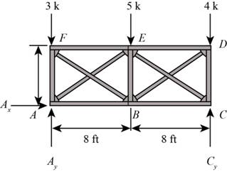
Figure-(1)
Write the equation for moment about A.
Here, vertical reaction at C is
Write the equation for sum of vertical forces.
Here, vertical reaction at A is
Substitute
Consider the force in diagonal members FB is in tension and AE is in compression.
Here, force in member AE and FB are
Use the method of section and cut the section as shown in figure below and calculate the forces in the members.
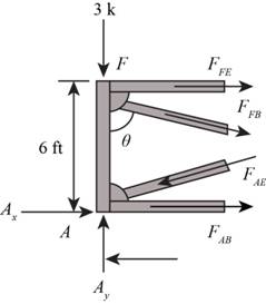
Figure-(2)
Calculate the angles as shown below.
Here, the angle between the members FA and FB is
Consider the joint F.
Write the Equation for sum of vertical forces.
Substitute
Write the equation for the sum of horizontal forces.
Here, force in member FE is
Substitute
Consider joint A.
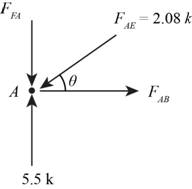
Figure-(3)
Calculate the angles as shown below.
Write the equation for sum of vertical forces.
Substitute
Here, force in member FA is
Write the Equation for sum of horizontal forces.
Substitute
Here, force in member AB is
Consider the force in diagonal members BD is in tension and EC is in compression.
Here, force in member BD and EC are
Use the method of section method and cut the section as shown in figure below and calculate the forces in the members.
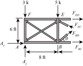
Figure-(4)
Calculate the angles as shown below.
Write the Equation for sum of vertical forces.
Substitute
Here, force in the member BD and CE are
Write the equation for moment about B.
Here, force in the member ED is
Substitute
Write the Equation for moment about E.
Here, force in the member BC is
Substitute
Write the Equation for sum of vertical forces.
Substitute
Here, force in the member BE is
Consider the joint C.
Angles will be same as calculated at joint B.
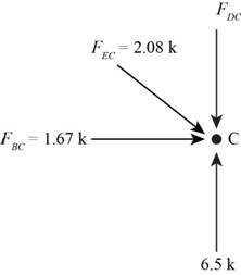
Figure-(5)
Write the Equation for sum of vertical forces.
Here, force in the member CD is
Substitute
Conclusion:
Therefore, the forces in each member of the truss are shown below.
The force in member AE is,
The force in member BF is,
The force in member EF is,
The force in member AB is,
The force in member CE is,
The force in member BD is,
The force in member DE is,
The force in member BC is,
The force in member AF is,
The force in member BE is,
The force in member CD is,
Want to see more full solutions like this?
Chapter 12 Solutions
Structural Analysis (10th Edition)

- Convert the Followingarrow_forwardSolve for the following right triangle for missing parts: - Angle A - Angle B - Side a - Areaarrow_forwardYOUR TOP STADIA CROSSHAIR IN YOUR LEVEL YEILDS A Roo READING of 7.32 FT. YOUR BOTTOM STADIA CROSSHAIR READS 6.23 FT. How FAR AWAY FROM YOUR INSTRUMENT (LEVEL) IS YOUR STATION WHERE YOUR PHilly Roo IS LOCATED:arrow_forward
- SITUATION. A uniform live load of 16 kN/m and a single concentrated live force of 34 kN are placed on the top beams. If the beams also support a uniform dead load of 3 kN/m, determinearrow_forwardComplete the profile leveling notes in Table 1. Show the arithmetic check and sample calculations of your work. Draw a neat sideview sketch showing the location of all stations and indicate on the sketch all of the numbers in your completed table.arrow_forward3. A level loop was run starting at BM 20 and going clockwise around the loop shown below in Figure 2. The given known elevation of BM 20 is 1418.013 ft. When closing the level loop, BM 20 was found to have an elevation of 1417.890 ft. (a) Adjust the elevation of each station to correct for error. Show sample calculations of your work. (b) What is the accuracy ratio of the survey? BM 20 Elev. 1418.013 2.3 mi BM 20A Observed Elev. 1234.567 2.7 mi 1.6 mil 0.9 mi BM 20B Observed Elev. 1357.913 BM 20C Observed Elev. 1396.963arrow_forward
- A W14 x 82 with 20 ft length column is part of a braced frame. The load and moments computed from service loads, and bending is about the x axis are (axial compressive dead load of 63 k; axial compressive live load of 76 k; upper dead moment of 32 ft-k; upper live moment of 56 ft-k; lower dead moment of 65 ft-k; lower live moment of 95 ft-k; the moments cause the member to bend in double curvature). Determine the lateral-torsional buckling modification factor C₁. ial live load ofarrow_forwardPROBLEM 1 Find the reaction at A and F. Compute for the force in members AB, BD, and DF. Use Method of Joints OR Method of Sections OR both. 3m B D C E 3m 100KN 3m 4marrow_forwardI need detailed help solving this exercise from homework of Engineering Mathematics II.I do not really understand how to do, please do it step by step, not that long but clear. Thank you!P.S.: Please do not use AI, thanks!arrow_forward

 Structural Analysis (10th Edition)Civil EngineeringISBN:9780134610672Author:Russell C. HibbelerPublisher:PEARSON
 Principles of Foundation Engineering (MindTap Cou...Civil EngineeringISBN:9781337705028Author:Braja M. Das, Nagaratnam SivakuganPublisher:Cengage Learning
 Fundamentals of Structural AnalysisCivil EngineeringISBN:9780073398006Author:Kenneth M. Leet Emeritus, Chia-Ming Uang, Joel LanningPublisher:McGraw-Hill Education
 Traffic and Highway EngineeringCivil EngineeringISBN:9781305156241Author:Garber, Nicholas J.Publisher:Cengage Learning