The forces in each member of the truss.
Answer to Problem 12.1P
The forces in each member of the truss are shown below.
The force in member AE is,
The force in member BF is,
The force in member EF is,
The force in member AB is,
The force in member CE is,
The force in member BD is,
The force in member DE is,
The force in member BC is,
The force in member AF is,
The force in member BE is,
The force in member CD is,
Explanation of Solution
Check the determinacy of the truss as shown below.
Here, number of members are
Substitute
Hence, the given truss is statically indeterminate by
The following diagram shows the free body diagram of the truss.
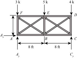
Figure-(1)
Write the equation for moment about A.
Here, vertical reaction at C is
Write the equation for sum of vertical forces.
Here, vertical reaction at A is
Substitute
Consider the force in diagonal members FB is in tension and AE is in compression.
Here, force in member AE and FB are
Use the method of section and cut the section as shown in figure below and calculate the forces in the members.
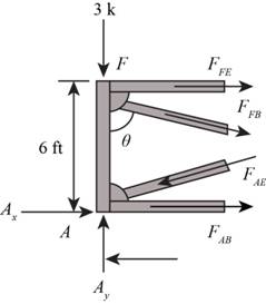
Figure-(2)
Calculate the angles as shown below.
Here, the angle between the members FA and FB is
Consider the joint F.
Write the Equation for sum of vertical forces.
Substitute
Write the equation for the sum of horizontal forces.
Here, force in member FE is
Substitute
Consider joint A.
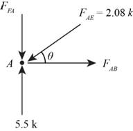
Figure-(3)
Calculate the angles as shown below.
Write the equation for sum of vertical forces.
Substitute
Here, force in member FA is
Write the Equation for sum of horizontal forces.
Substitute
Here, force in member AB is
Consider the force in diagonal members BD is in tension and EC is in compression.
Here, force in member BD and EC are
Use the method of section method and cut the section as shown in figure below and calculate the forces in the members.
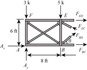
Figure-(4)
Calculate the angles as shown below.
Write the Equation for sum of vertical forces.
Substitute
Here, force in the member BD and CE are
Write the equation for moment about B.
Here, force in the member ED is
Substitute
Write the Equation for moment about E.
Here, force in the member BC is
Substitute
Write the Equation for sum of vertical forces.
Substitute
Here, force in the member BE is
Consider the joint C.
Angles will be same as calculated at joint B.
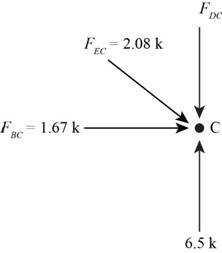
Figure-(5)
Write the Equation for sum of vertical forces.
Here, force in the member CD is
Substitute
Conclusion:
Therefore, the forces in each member of the truss are shown below.
The force in member AE is,
The force in member BF is,
The force in member EF is,
The force in member AB is,
The force in member CE is,
The force in member BD is,
The force in member DE is,
The force in member BC is,
The force in member AF is,
The force in member BE is,
The force in member CD is,
Want to see more full solutions like this?
Chapter 12 Solutions
Structural Analysis, Student Value Edition Plus Mastering Engineering With Pearson Etext -- Access Card Package (10th Edition)

- If you could help me answer these questions in matlab that would be great, I provided an additional picture detailing what the outcome should look like.arrow_forwardA fully grouted reinforced masonry wall is to be constructed of 8-in. CMU. The wall height is 18feet. It is assumed to be simply supported. The wall is to be designed for an out-of-plane seismicload of 52 lbs./ft.2, which can act in either direction. The wall also supports a roof dead load of600 lbs./ft. and a roof live load of 300 lbs./ft. along the wall length. The roof loads have aneccentricity of 2.5 inches. Since there is seismic load, load combinations (6) and (7) in Chapter 2of ASCE 7-22 should be considered. In these two load combinations,horizontal seismic loadhE =andvertical seismic loadvE = . You may ignorevE in this problem for simplicity. The masonryhas a specified compressive strength of 2,500 psi. (a) Use the strength design provisions of TMS402 to determine the size and spacing of the vertical bars needed. Use the P-δ analysis method inSection 9.3.4.4.2 of TMS 402 to determine Mu. (b) Repeat the design using the momentmagnification method in Section 9.3.4.4.3 instead.arrow_forwardThe factor of safety for tipping of the concrete dam is defined as the ratio of the stabilizing moment due to the dam's weight divided by the overturning moment about OO due to the water pressure (Figure 1). Suppose that aa = 5 mm , dd = 2 mm , hh = 7 mm . The concrete has a density of ρconcρconc = 2.5 Mg/m3Mg/m3 and for water ρwρw = 1 Mg/m3Mg/m3arrow_forward
- can you answer both plss, i will give u a likearrow_forward*1-4. The hollow core panel is made from plain stone concrete. Determine the dead weight of the panel. The holes each have a diameter of 100 mm. 200 mm 300 mm 300 mm 300 mm 300 mm 300 mm Prob. 1-4 300 mm 4 marrow_forwardderive the expressions for V and M, and draw the shear forceandbendingmomentdiagrams.Neglecttheweightofthebeam.arrow_forward
- a. Draw trajectories of approximately 8 to 11 vehicles moving on a one way 1-lane road with different time-varying speeds. b. Consider a time-space window in the time-space diagram of part (a). See below. Denote the number of vehicles passing BD, DC, AC, and AB respectively as n1, N2, N3, and n4. Write an equation relating n₁, N2, N3, and n4 to each other. What is the physical intuition of this equation? Please elaborate. X 4 X. n4 n3 с n2 X1 D B n1 t c. Using density (k) definition at time instances t₁ and t₂ and flow (q) definition at locations X1 and X2, rewrite equation of interest in part (b) to demonstrate KAB-KCD 9BD-9AC + t₂-t1 x2-x1 = 0. d. What will be the equation in part (c), in case of x2 → x1 and t₂ → t₁.arrow_forwardConsider a city center where the traffic conditions are described by a Macroscopic Fundamental Diagram (MFD) of network outflow (g- rate of trips finished) vs. accumulation (n- number of cars) with a trapezoidal shape, as shown in the figure below. The values of the parameters are: • • maximum trip completion rate gmax=100 [veh/min] critical accumulations ncr1=1000 [veh] and ncr2=1500 [veh] jam accumulation njam=4000 [veh]. gmax ncr1 ncr2 njam There are two types of demands in the morning peak hour (7-8am): trips generated from outside the city center with rate q1=80 [veh/min], and trips generated from within the city center with rate q2=50 [veh/min]. In addition, a perimeter traffic control, u, is available that only restricts vehicles entering the city from outside. If at 7am there are already no=500 [veh] in the city center: a. Write the dynamic equations (mass conservation equation) in a continuous form for the center of the city. b. Convert the continuous dynamic into the discrete…arrow_forwardAssume a car park facility where the arrival rate is 1 customer every minute, and the service process including pressing the button, taking the card, and waiting for the boom to rise leads to service rate of μ customer every minute. a. Assume the arrival and service processes are stochastic. Using any software (Excel, Matlab, or the one you prefer), plot average delay time (including service time) and average queue size (including the vehicle currently being served) for all combinations of λ = {1,2,3,..,10} and p = {0.1,0.3,0.5,0.7,0.9}. Specifically, we ask you to make 2 graphs (one for average delay and the other for average queue size), where the x-axes contains the different values for 1, and where you make one curve for each p. b. Assume the arrival process is stochastic but the service process is deterministic with rate μ. Using any software (Excel, Matlab, or the one you prefer), plot average delay time (including service time) and average queue size (including the vehicle…arrow_forward
- A traffic signal has a 60-second cycle length (Red time + Green time). For the travel direction of interest, the red and green times are 30 seconds each, the arrival rate is constant at 20 [veh/min] and the saturation flow (i.e., the departure rate) is 1 [veh/sec]. a. Calculate the average delay (for all vehicles) for the travel direction of interest. b. Assume a work zone on the street downstream of the intersection so that only 25 [veh/min] (in the direction of interest) can pass. Calculate the average delay caused by the work zone to a vehicle leaving the intersection. Assume that the queue at the work zone never backs- up into the intersection. c. Discuss qualitatively the implications of queue spillback from the work zone on the delay of the system. Traffic Direction (a) Traffic Direction (b)arrow_forwardAttached pics is a sample problem, can you compute it for me, I just want to compare my answer. Thank you.arrow_forwardProblem 2: The Douglas fir beam below supports uniform live (WL) and dead loads (WD) as shown below. Assume the total distributed load is 700 lb/ft. WD=300#/PT. W₁ = 400# W₁ = 400#/FT- J J J J I J J J L=161 a) Assuming an alllowable deflection of L/360, compute the magnitude of the allowable deflection. b) Using an 8"x12" timber beam (see Table A1-b on page 567 of your text for properties) compute the actual deflection. Assume E = 1.6 x 100 psi. c) Based on your answers for parts a and b, determine if an 8"x12" timber beam is safe for this applicationarrow_forward

 Structural Analysis (10th Edition)Civil EngineeringISBN:9780134610672Author:Russell C. HibbelerPublisher:PEARSON
 Principles of Foundation Engineering (MindTap Cou...Civil EngineeringISBN:9781337705028Author:Braja M. Das, Nagaratnam SivakuganPublisher:Cengage Learning
 Fundamentals of Structural AnalysisCivil EngineeringISBN:9780073398006Author:Kenneth M. Leet Emeritus, Chia-Ming Uang, Joel LanningPublisher:McGraw-Hill Education
 Traffic and Highway EngineeringCivil EngineeringISBN:9781305156241Author:Garber, Nicholas J.Publisher:Cengage Learning