
Mechanics of Materials Plus Mastering Engineering with Pearson eText - Access Card Package (10th Edition)
10th Edition
ISBN: 9780134518121
Author: Russell C. Hibbeler
Publisher: PEARSON
expand_more
expand_more
format_list_bulleted
Concept explainers
Videos
Textbook Question
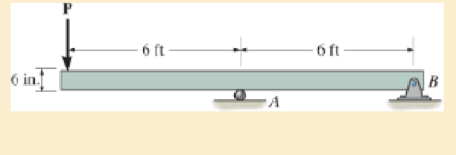
Chapter 11.2, Problem 11.3P
if P=10 kip.
Expert Solution & Answer

Trending nowThis is a popular solution!

Students have asked these similar questions
Bolted Joint Design
Bolted Frames
Total Force due to door weight: P =
240
lb
Number of Bolts: N =
Distance to Bolt C/L: a =
4
N/A
Bolt Material -
Allowable shear stress of bolt material: T₂ =
x Distance from Bolt centroid to bolt: x =
y Distance from Bolt centroid to bolt: y =
Degrees per Radian-
Results
y-Load on each bolt: F, =
Moment resisted by bolt pattern: M =
Radial distance from Bolt centroid to bolt: r =
Sum squares of all radial distances: Σr²
Force on each bolt to resist moment: F, -
Angle for force composition: e=
X-Force on each bolt to resist moment: F-
y-Force on each bolt to resist moment: Fly
Total y-Force on each bolt: Fy =
Resultant force on bolt 1: R₁ =
Required shear stress area for a bolt: A₂ =
ASTM Grade
A307 Steel
10,000
0
psi
from Table 20-1
3.0
57.296
in
degrees
lb per bolt
lb-in
Formula
FS-P/N
M-Px XB
r = (x² + y²)0.5
in²
Σ
4r²
Mr
F₁ =
Στ
lb
degrees
lb
lb
lb
Minimum Bolt Diameter: Din =
Rounded up Bolt Diameter: D =
55
P.
1.5 in
2 in (3x)
1 in
This bracket…
University of Babylon
Collage of Engineering/
Al-Musayab
Department of Automobiles
Final Examination/ Stage: 3rd
Notes:
Answer 4 questions only
2023-2202
Subject: Theory of vehicles
Date: 2023\06\10-Saturday
Time: Three Hours
Course 2nd Attempt 1st
Q1: A Hooke's coupling connects two shafts whose axes are inclined at 30°. The
of the driven shaft? Find the maximum value of retardation or acceleration and
driving shaft rotates uniformly at 600 rpm. What are the extreme angular velocities
state the angle where both will occur.
(12.5 Marks)
Q2: Four masses, A, B, C, and D), revolve at equal radii and are equally spaced
along a shaft. The mass B is 7 kg, and the radius of C and D make angles of 90°
and 240°, respectively, with the radius of B. Find the magnitude of the masses A,
C, and D and the angular position of A so that the system may be completely
balanced.
(12.5 Marks)
Q3: A cam has straight worked faces that are tangential to a base circle of diameter
90 mm. The follower is a roller…
Problem 18-26
Added
Extension Springs
Spring Material
ASTM A227
Modulus of Elasticity of the Material in Shear: G 1.150E+07 psi
Average Service
Max Operating Load: F₁ =
100
lb
Max Length between attachment points: L₁ =
60.00 in
20.00 lb
26.00
1.400
Min Operating Load: F₁ =
Min Length between attachment points: L₁ =
Maximum Outside Diameter =
in
in
Results
Note: you select a wire diameter from the "US steel wire gage"
column in table 18-2
Formula
k =
AF/AL
k = (F0-F1)/(Lo - L₁)
Spring Rate: k =
lb/in
Assumed Trial Outside Diameter: OD =
Assumed Trial Mean: D ma
Assumed Design Stress in Spring: Tda
in
1.070
in
102,000 psi
Assumed Wahl Factor: K =
1.2
Calculated Wire Diameter: Dwa
Actual Wire Diameter: Dw
Actual outer diameter: OD =
Actual inner diameter: ID=
Spring Index: C =
See Figure 18-8
Dw=
[8KF Dm
πTd
1/3
in
5' 5' 5' 5'
This corresponds to US Steel 9 wire gage
ID = Dm - Dw
C = Dm/Dw
4C - 1
0.615
K =
+
4C
-
с
Wahl Factor: K =
8KFDm
8KFC
T =
TD
πD
Stress in Spring at F = Fo: To
psi…
Chapter 11 Solutions
Mechanics of Materials Plus Mastering Engineering with Pearson eText - Access Card Package (10th Edition)
Ch. 11.2 - Determine the minimum dimension a to the nearest...Ch. 11.2 - of the rod to safely support the load. The rod is...Ch. 11.2 - The wood has an allowable normal stress of allow =...Ch. 11.2 - of the beam's cross section to safely support the...Ch. 11.2 - Determine the minimum dimension b to the nearest...Ch. 11.2 - The beam is made of steel having an allowable...Ch. 11.2 - Determine its dimensions if it is to be...Ch. 11.2 - Determine the minimum width of the beam to the...Ch. 11.2 - if P=10 kip.Ch. 11.2 - If the allowable bending stress is allow = 22 ksi...
Ch. 11.2 - The allowable bending stress is allow = 24 ksi and...Ch. 11.2 - The allowable bending stress is allow = 22 ksi and...Ch. 11.2 - The allowable bending stress is allow = 24 ksi and...Ch. 11.2 - Select the lightest-weight wide-flange beam from...Ch. 11.2 - The beam has an allowable normal stress of allow =...Ch. 11.2 - The beam has an allowable normal stress of allow...Ch. 11.2 - If each nail can support a shear force of 200 lb....Ch. 11.2 - If each beam is to be designed to carry 90 lb/ft...Ch. 11.2 - Determine its height h so that it simultaneously...Ch. 11.2 - The beam is constructed from four boards. If each...Ch. 11.2 - Prob. 11.15PCh. 11.2 - The beam has an allowable normal stress of allow....Ch. 11.2 - Determine the maximum cable force P that can...Ch. 11.2 - to safely support the load. The wood has an...Ch. 11.2 - and the wood has an allowable normal stress of...Ch. 11.2 - If the glue can support a shear stress of allow, =...Ch. 11.2 - If the allowable bending stress is allow = 6 MPa,...Ch. 11.2 - Determine the width b if the height h=2b.Ch. 11.2 - The allowable bending stress is allow = 24 ksi and...Ch. 11.2 - if allow = 30 ksi and allow = 15 ksi. The journal...Ch. 11.2 - if allow = 30 ksi and allow = 15 ksi. The journal...Ch. 11.2 - Select the lightest-weight wide-flange beam from...Ch. 11.2 - The allowable bending stress is allow = 30 ksi and...Ch. 11.2 - The allowable bending stress is allow = 30 ksi and...Ch. 11.2 - If the maximum bending stress is not to exceed...Ch. 11.2 - Determine the maximum load that can safely be...Ch. 11.4 - Determine the variation in the width was a...Ch. 11.4 - The tapered beam supports a uniform distributed...Ch. 11.4 - The tapered beam supports the concentrated force P...Ch. 11.4 - The beam is made from a plate that has a constant...Ch. 11.4 - Determine the variation in the depth d of a...Ch. 11.4 - Determine the variation of the radius r of the...Ch. 11.4 - Prob. 11.37PCh. 11.4 - Determine the variation in the width b as a...Ch. 11.4 - The tubular shaft has an inner diameter of 15 mm....Ch. 11.4 - Prob. 11.40PCh. 11.4 - Prob. 11.41PCh. 11.4 - The pulleys fixed to the shaft are loaded as...Ch. 11.4 - Prob. 11.43PCh. 11.4 - Prob. 11.44PCh. 11.4 - Prob. 11.45PCh. 11 - The cantilevered beam has a circular cross...Ch. 11 - Select the lightest-weight wide-flange overhanging...Ch. 11 - Prob. 11.3RPCh. 11 - Determine the shaft's diameter to the nearest...Ch. 11 - Select the lightest-weight wide-flange beam from...Ch. 11 - The simply supported joist is used in the...Ch. 11 - The simply supported joist is used in the...Ch. 11 - by 4-in. pieces of wood braced as shown. If the...
Additional Engineering Textbook Solutions
Find more solutions based on key concepts
A nozzle at A discharges water with an initial velocity of 36 ft/s at an angle with the horizontal. Determine ...
Vector Mechanics For Engineers
Why is the study of database technology important?
Database Concepts (8th Edition)
17–1C A high-speed aircraft is cruising in still air. How does the temperature of air at the nose of the aircra...
Thermodynamics: An Engineering Approach
How are relationships between tables expressed in a relational database?
Modern Database Management
The following C++ program will not compile because the lines have been mixed up. cout Success\n; cout Success...
Starting Out with C++ from Control Structures to Objects (9th Edition)
The job of the _____ is to fetch instructions, carry out the operations commanded by the instructions, and prod...
Starting Out With Visual Basic (8th Edition)
Knowledge Booster


Learn more about
Need a deep-dive on the concept behind this application? Look no further. Learn more about this topic, mechanical-engineering and related others by exploring similar questions and additional content below.Similar questions
- CHAIN DRIVE DESIGN Initial Input Data: Application: Garage Door Opener Drive type: AC Motor Driven machine Chain and Sprocket to pull the door up Degrees per Radian: 57.2958 degrees Sprocket Diameter: D = 1.690 in Number of strands: Chain number: 1 40 Service factor: 1.3 Table 7-10 No. of teeth Computed Data: Actual Motor Power Input: 0.000 hp Sprocket Speed (for sprocket attached to gear shaft) Design power: 0.00 rpm 0 hp 11 12 0.06 0.15 0.29 0.56 0.99 1.09 1.61 2.64 TABLE 7-7 Horsepower Ratings-Single Strand Roller Chain No. 40 0.500 inch pitch 10 25 50 100 180 200 300 500 700 900 1000 1: 0.06 0.14 0.27 0.52 0.91 1.00 1.48 2.42 3.34 4.25 4.70 ! 3.64 4.64 5.13 13 0.07 0.16 0.31 0.61 1.07 1.19 1.75 2.86 3.95 5.02 5.56 Design Decisions-Chain Type and Teeth Numbers: 14 Chain number: Use Table 7-7 Chain pitch: p = in 15 Number of Teeth: N = Per Table 7-7 16 0.08 0.20 0.39 0.75 1.32 1.46 2.15 3.52 0.07 0.17 0.34 0.66 1.15 1.28 1.88 3.08 0.08 0.19 0.36 0.70 1.24 1.37 2.02 3.30 4.55 5.80…arrow_forwardInput Data: Torque needed to overcome rolling friction in rollers, slides and other moving parts, except for Motor and Worm Gear the worm gear T₁ = Length of travel of door: Time for door to open or close: LD = 50 lb-in. 90 in t= 12.5 seconds Pitch diameter for chain sprocket: DPC 1.690 in Weight of Door: P = No. of worm threads: Nw = Worm Pitch diameter: Dw Diametral pitch: Pd Normal pressure angle: Degrees per Radian: Number of gear teeth: Calculated Data: Linear velocity of door and chain (in/sec): Linear velocity of door and chain (ft/min): Output Speed of Gear and Sprocket: Upward Force due to Weight of Door: Фо = = NG= 240 lb 2 1.250 in 12 14.5 degrees 57.2958 degrees 28 Vα= in/sec VC= ft/min NG = rpm FD lb Net Upward Force on Door: Fou lb Torque on gear ignoring rolling friction: TG = lb-in. Formula = FDU FD-2 x Fo (note: Fo is the Max Operating load of the extension springs). This is also the initial tension in the chain. TG = FDU X DPC/2 This is the also the torque on the…arrow_forwardQ5/A: A car with a track of 1.5 m and a wheelbase of 2.9 m has a steering gear mechanism of the Ackermann type. The distance between the front stub axle pivots is 1.3 m. The length of each track arm is 150 mm, and the length of the track rod is 1.2 m. Find the angle turned through by the outer wheel if the angle turned through by the inner wheel is 30°. (6 Marks) Q5/B: Write True on the correct sentences and False on the wrong sentences listed below:- 1- In automobiles, the power is transmitted from the gearbox to the differential through bevel gears. 2- The minimum radius circle drawn to the cam profile is called the base circle. 3- The Proell governor, compared to the Porter governor, has less lift at the same speed. 4- The balancing of rotating and reciprocating parts of an engine is necessary when it runs at a slow speed. (6.5 Marks) ***Best of Luck *** جامعة بابل UNIVERSITY OF BABYLON Examiner: Mohanad R. Hameed Head of Department: Dr. Dhyai H. Jawadarrow_forward
- University of Babylon Collage of Engineering/ Al-Musayab Department of Automobiles Mid Examination/ Stage: 3rd Subject: Theory of Vehicles Date: 14 \ 4 \2025 Time: 1.5 Hours 2025-2024 Q1: The arms of a Porter governor are 250 mm long. The upper arms are pivoted on the axis of revolution, but the lower arms are attached to a sleeve at a distance of 50 mm from the axis of rotation. The weight on the sleeve is 600 N and the weight of each ball is 80 N. Determine the equilibrium speed when the radius of rotation of the balls is 150 mm. If the friction is equivalent to a load of 25 N at the sleeve, determine the range of speed for this position. Q2: In a loaded Proell governor shown in Figure below each ball weighs 3 kg and the central sleeve weighs 25 kg. The arms are of 200 mm length and pivoted about axis displaced from the central axis of rotation by 38.5 mm, y=238 mm, x=303.5 mm, CE 85 mm, MD 142.5 mm. Determine the equilibrium speed. Fe mg E M 2 Q3: In a spring loaded Hartnell type…arrow_forwardusing the theorem of three moments, find all the reactions and supports, I need the calculations onlyarrow_forwardQ.5: (10 Marks) Select the correct answer (choose 10 only) 1. The forward whirling speed is ......... the static structure tilting speed. (a) Less than (b) Higher than (c) equal to 2. The divergence between the forward and backward whirling speeds increases as: (a) The rotating speed increase (b) the polar moment of inertia increases (c) Both (a) and (b) (d) do not change 3. Increasing the system natural frequency can be done by: (a) add masses (b) adding braces and supports (c) increase damping 4. The amplitude of vibration due to external force can be reduced by: (a) Increasing damping (b) Decreasing damping (c) Increasing mass 5. Tuned absorbers are used to: (a) Shift the natural frequency (b) increase damping (c) Increase stiffness 6. Accelerometers sensors contains: г (a) Piezoelectric materials (b) Magnet and coil (c) coil only 7. Increasing the stiffness of the system causes: (a) Less transmitted force (b) more transmitted force (c) Transmitted force does not change 8. The…arrow_forward
- Q.1: (15 Marks) Find the first three natural frequencies and mode shapes of the axial and torsional vibration for a steel shaft free at both ends, having a length of 3 m. Find the subsequent axil motion if the shaft is subjected to the following initial conditions, given that E = 210 GPa, G=80 GPa, p = 7800 kg/m³: f(x)=0 v(x) = {1 2.8arrow_forwardQ.4: (15 Marks) A uniform rotor of mass 500 kg and diametral moment of inertia of 20 kg.m², is supported by identical short bearings of stiffness 1 MN/m in the horizontal and vertical directions. If the distance between the bearings is 0.6 m: (a) What is the corresponding polar moment of inertia if the backward whirling speed is 80% of the static structure tilting natural frequency? (b) Determine the forward whirling speed. 45.27arrow_forwardUniversity of Babylon Collage of Engineering/ Al-Musayab Department of Automobiles Mid Examination/ Stage: 3rd Subject: Theory of Vehicles Date: 14 \ 4 \2025 Time: 1.5 Hours 2025-2024 Q1: The arms of a Porter governor are 250 mm long. The upper arms are pivoted on the axis of revolution, but the lower arms are attached to a sleeve at a distance of 50 mm from the axis of rotation. The weight on the sleeve is 600 N and the weight of each ball is 80 N. Determine the equilibrium speed when the radius of rotation of the balls is 150 mm. If the friction is equivalent to a load of 25 N at the sleeve, determine the range of speed for this position. Q2: In a loaded Proell governor shown in Figure below each ball weighs 3 kg and the central sleeve weighs 25 kg. The arms are of 200 mm length and pivoted about axis displaced from the central axis of rotation by 38.5 mm, y=238 mm, x=303.5 mm, CE 85 mm, MD 142.5 mm. Determine the equilibrium speed. Fe mg E M 2 Q3: In a spring loaded Hartnell type…arrow_forwardQ.2: (15 Marks) = 1400 For the following system, determine the first natural frequency using Dunkerley's equation, Given that the disk has moment of inertia J = 2 kg.m², the shaft has G = 20 GPa, p kg/m³, polar moment of cross-sectional area of the shaft Ip = 8×10⁸ m². 500 mm 220 mm k=200 N/m FOF m=1 kg 14.14 56.56. W слarrow_forwardQ.2: (15 Marks) = 1400 For the following system, determine the first natural frequency using Dunkerley's equation, Given that the disk has moment of inertia J = 2 kg.m², the shaft has G = 20 GPa, p kg/m³, polar moment of cross-sectional area of the shaft Ip = 8×10⁸ m². 500 mm 220 mm k=200 N/m FOF m=1 kg 14.14 56.56. W слarrow_forwardQ1: In Figure below, pinion A having 15 teeth is fixed to motor shaft. Za-20, Z-15, where B and C are a compound gear wheel. Wheel E is keyed to the machine shaft. Arm F rotates about the same shaft on which A is fixed and carries the compound wheel B, C. If the motor runs at 1200 rpm counter-clockwise, find (a) the speed of the machine shaft and (b) ratio of the reduction gear. C B D Q1: A compound epicyclic gear is shown diagrammatically in Figure below. The gears A, D and E are free to rotate on the axis P. The compound gear B and C rotate together on the axis Q at the end of arm F. All the gears have equal pitch. The number of external teeth on the gears A, B and C are 18, 45 and 21 respectively. The gears D and E are annular gears. The gear A rotates at 100 r.p.m. in the anticlockwise direction and the gear D rotates at 450 r.p.m. clockwise. Find the speed and direction of the arm and the gear E. D E A P F LL B Carrow_forwardarrow_back_iosSEE MORE QUESTIONSarrow_forward_ios
Recommended textbooks for you
 International Edition---engineering Mechanics: St...Mechanical EngineeringISBN:9781305501607Author:Andrew Pytel And Jaan KiusalaasPublisher:CENGAGE L
International Edition---engineering Mechanics: St...
Mechanical Engineering
ISBN:9781305501607
Author:Andrew Pytel And Jaan Kiusalaas
Publisher:CENGAGE L
Stresses Due to Fluctuating Loads Introduction - Design Against Fluctuating Loads - Machine Design 1; Author: Ekeeda;https://www.youtube.com/watch?v=3FBmQXfP_eE;License: Standard Youtube License