
Electrical Wiring Residential
18th Edition
ISBN: 9781285170954
Author: Ray C. Mullin, Phil Simmons
Publisher: Cengage Learning
expand_more
expand_more
format_list_bulleted
Concept explainers
Videos
Textbook Question
Chapter 11, Problem 9R
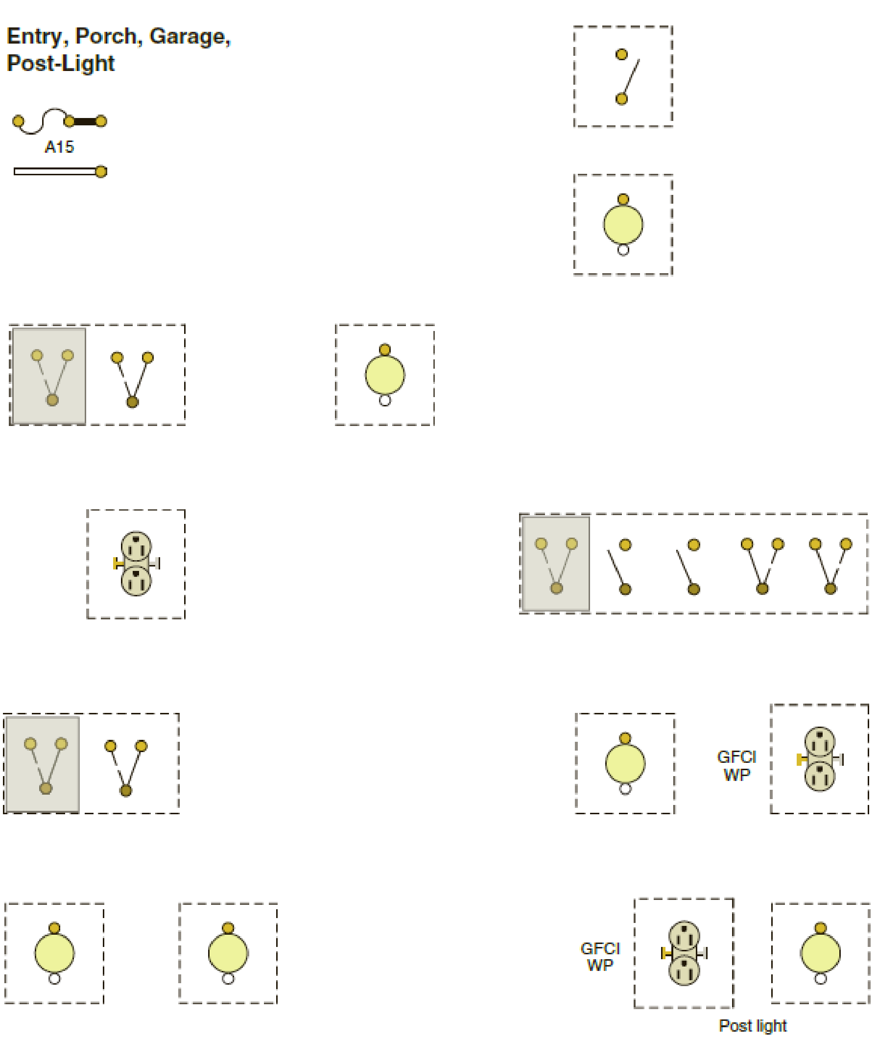
The following layout is for Lighting Circuit A15, the entry, porch, post light, and front garage lights. Using the cable layout shown in Figure 11-1, make a complete wiring diagram of this circuit. Use colored pencils to indicate the color of the conductors’ insulation.
Expert Solution & Answer

Trending nowThis is a popular solution!

Students have asked these similar questions
Solve this problem and show all of the work
Q3: Why is the DRAM cell design simpler but slower than SRAM?
5052
ми
a
JXL
000
+2
16s (wt) bi
jxc
M
100♫
ZL.
Find the Value of XL & X c
if the Circuit trans for Max.
Power to (ZL).
Chapter 11 Solutions
Electrical Wiring Residential
Ch. 11 - How many circuit wires enter the entry ceiling...Ch. 11 - Assuming that an outlet box for the entry ceiling...Ch. 11 - How many receptacle outlets and lighting outlets...Ch. 11 - Outdoor luminaires directly exposed to the weather...Ch. 11 - Prob. 5RCh. 11 - From left to right, facing the switches, what do...Ch. 11 - Who is to select the entry ceiling luminaire? ____Ch. 11 - When installing the wiring for a doorjamb switch,...Ch. 11 - The following layout is for Lighting Circuit A15,...
Knowledge Booster


Learn more about
Need a deep-dive on the concept behind this application? Look no further. Learn more about this topic, electrical-engineering and related others by exploring similar questions and additional content below.Similar questions
- Choose the best answer for each: 1. What does SRAM use to store data? 。 a) Capacitors ob) Latches 。 c) Flip-flops od) Transistors 2. Which RAM type requires refreshing? o a) SRAM ob) DRAM 。 c) ROM od) Flash 3. What type of memory retains data only while power is on? a) ROM 。 b) EEPROM o c) DRAM od) Flash 4. How many addresses can a 15-bit address bus handle? o a) 32k • b) 64k o c) 16k od) lk 5. What operation occurs when data is copied out of memory without erasing? oa) Write ob) Read o c) Refresh o d) Load 6. DRAM cells store bits using: a) Flip-flops 。 b) Capacitors c) Diodes od) Resistors 7. The cache located inside the CPU is: 。 a) L2 cache o b) LI cache °c) ROM od) HDD 8. SDRAM is synchronized with: o a) Cache ob) Data Bus c) System Clock od) Hard Disk 9. The bus that carries commands is called: o a) Data Bus b) Control Bus o c) Address Bus o d) Logic Bus 10. What is the main use of SRAM? o Disk storage o Cache o Main memory o Registers 11. The smallest addressable unit in…arrow_forwardQ4: A cache memory is 128k × 16. How many bytes can it store?arrow_forwardSketch the output of the analogue computer shown below and find its closest describing function [suppose any variable to find the DF] +1 ew2 HI e2 1.0 +21 LO SJ eo SJ ew LO 1.0 +|e1| HI -1 ew1 ek(1 + e。) |e1| k = 1+|e1| Figure V-5 Feedback Limiter Behavior ROUNDED, DUE TO DIODE NONLINEARITY LIMIT VOLTAGE 409 DIODE CONDUCTS First, write the output transaction, then draw the output wave, and then find the Describing function. I need to solve the question step by step, with an explanation of each step.arrow_forward
- Sketch the output of the analogue computer shown below and find its closest describing function [suppose any variable to find the DF] SJ ew2 ew₁ HI |e2| 2 LO 1.0 +21 LO -1 HI Jel 1.0+|e1| ROUNDED, DUE TO DODE NONLINEARITY LIMIT VOLTAGE DIODE CONDUCTS ew1e, -k(1+ e。) k = |e1| 1+|e1| Figure 1-5 Feedback Limiter Behavior First, write the output transaction, then draw the output wave, and then find the Describing function. I need to solve the question step by step, with an explanation of each step.arrow_forwardSketch the output of the analogue computer shown below and find its closest describing function [suppose any variable to find the DF] SJ +1 HI LO e2 1.0 +21 ew2 eo SJ ew₁ LO Jel 1.0 +|e1| HI -1 ew1 ek(1+eo) k = |e1| 1+|e1| First, write the output transaction, then draw the output wave, and then find the Describing function. I need to solve the question step by step, with an explanation of each step.arrow_forwardCan you help me find the result of an integral 0/2 a² X + a dxarrow_forward
- Q1/Sketch the root locus for the system shown in Figure 1 and find the following: a. The exact point and gain where the locus crosses the jo-axis b. The breakaway point on the real axis c. The range of K within which the system is stable d. Angles of departure and arrival R(s) + K(s²-4s +20) C(s) (s+2)(s + 4)arrow_forwardExam2 Subject: (Numerical Analysis) Class: Third Date: 27/4/2025 Time: 60 minutes Q1. For what values of k does this system of equations has no solution? (use Gauss-Jordan eliminations) kx + y + z = 1 x+ky + z = 1 x+y+kz=1arrow_forwardConsider the Difference equation of a causal Linear time-invariant (LTI) system given by: (y(n) - 1.5y(n - 1) + 0.5y(n = 2) = x(n) a) Implement the difference equation model of this system. b) Find the system transfer function H(z). c) For an input x(n) = 8(n), determine the output response y(n). d) Verify the initial value theorem y(0) with part (c).arrow_forward
- Q5B. Find the type of the controller in the following figures and use real values to find the transfer function of three of them[ Hint Pi,Pd and Lead,lag are found so put the controller with its corresponding compensator]. R₁ R₂ Rz HE C2 RA HE R₁ R2 RA とarrow_forwardQ1// Sketch the root locus for the unity feedback system. Where G(s)=)= K S3+252 +25 and find the following a. Sketch the asymptotes b. The exact point and gain where the locus crosses the jo-axis c. The breakaway point on the real axis d. The range of K within which the system is stable e. Angles of departure and arrival.arrow_forwardDetermine X(w) for the given function shown in Figure (1) by applying the differentiation property of the Fourier Transform. Figure (1) -1 x(t)arrow_forward
arrow_back_ios
SEE MORE QUESTIONS
arrow_forward_ios
Recommended textbooks for you
 EBK ELECTRICAL WIRING RESIDENTIALElectrical EngineeringISBN:9781337516549Author:SimmonsPublisher:CENGAGE LEARNING - CONSIGNMENT
EBK ELECTRICAL WIRING RESIDENTIAL
Electrical Engineering
ISBN:9781337516549
Author:Simmons
Publisher:CENGAGE LEARNING - CONSIGNMENT
Types of House Wiring - Types of Electrical Wiring - Electrical Wiring; Author: Learning Engineering;https://www.youtube.com/watch?v=A5P-buWX-dA;License: Standard Youtube License