
Concept explainers
Videos
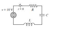
(a) Solve the equation for t in terms of L, R, C, and t, assuming that at t = 0, i = 0, and di/dt,= 8.
(b) Use the subs command to substitute L = 3 H. R = 10O, and C = 80 µF into the expression that was derived in part (a). Make a plot of i versus t for
(c) Use the subs command to substitute L = 3 H, R = 200 O, and C = l200µF into the expression that was derived in part (a). Make a plot of i versus t for
(d) Use the subs command to substitute L = 3 H, R = 201 O, and C = 300µF into the expression that was derived in pan (a). Make a plot of i versus t for
Want to see the full answer?
Check out a sample textbook solution
Chapter 11 Solutions
Matlab


- Alternator has star-connected,4-pole, 50 Hz as the following data: Flux per pole-0.12 Wb; No. of slot/pole/phase=4; conductor/slot=4; Each coil spans 150° (electrical degree) pitches Find (i) number of turns per phase (ii) distribution factor (iii) pitch factor (iv) no-load phase voltage (v) no-load line voltage.arrow_forwardAlternator has star-connected,4-pole, 50 Hz as the following data: Flux per pole-0.12 Wb; No. of slot/pole/phase=4; conductor/slot=4; Each coil spans 150° (electrical degree) pitches Find (i) number of turns per phase (ii) distribution factor (iii) pitch factor (iv) no-load phase voltage (v) no-load line voltage.arrow_forwardA) Suppose you were desiging a circuit that required two LEDs for "power on" indication. The power supply voltage is 5 volts, and each LED is rated at 1.6 volts and 20 mA. Calculate the dropping resistor sizes and power ratings: B) After doing this, a co-worker looks at your circuit and suggests a modification. Why not use a single dropping resistor for both LEDs, economizing the number of components necessary? Re-calculate the dropping resistor ratings (resistance and power) for the new design. Include the total power consumed by the circuit and the power delivered by the source.arrow_forward
- S A L ined sove in peaper ۳/۱ 16852 Alternator has star-connected,4-pole, 50 Hz as the following data: Flux per pole-0.12 Wb; No. of slot/pole/phase-4; conductor/slot-4; Each coil spans 150° (electrical degree) pitches Find (i) number of turns per phase (ii) distribution factor (iii) pitch factor (iv) no-load phase voltage (v) no-load line voltage. 2ci25 750 r 2.01 ४arrow_forwardA) Complete the table of values for this circuit: B) Draw the schematic include polarityarrow_forward(choose R1, R2, R3, R4, R5 and assume that 300 β = , all resistors must be greater than zero) such that the following specifications are met: • Minimum open loop gain, Aol, 40dB (can be more, this is the minimum requirement) • Input current (at input terminals) <1uA • Power dissipation DC P ≤20mW • VCC=10V, VEE=0VI NEED HELP, I WANT ONLY TO CALCULATE THE RESISTORSarrow_forward
- 80 V 300 Ω t = 0 500 i(t) Vc(t) 40 nF 2,5 mH -arrow_forwardProblem 1: Two-Force Equilibrium A 12 kg traffic light is suspended by two cables attached to a ceiling. Determine the force in Cable 1 (AB) and Cable 2 (AC). In other words, determine the tension in each cable, assuming the system is in static equilibrium. Barrow_forwardIf the Z-axis changes, what is the effect A circularly polarized wave, traveling in the +z-direction, is received by an elliptically polarized antenna whose reception characteristics near the main lobe are given approx- imately by E₁ = (2â, + jâ] f(r. 8. d) Find the polarization loss factor PLF (dimensionless and in dB) when the incident wave is (a) right-hand (CW) (b) left-hand (CCW) An elliptically polarized wave traveling in the negative z-direction is received by a circularly polarized antenna. The vector describing the polarization of the incident wave is given by Ei= 2ax + jay .Find the polarization loss factor PLF (dimensionless and in dB) when the wave that would be transmitted by the antenna is (a) right-hand CP (b) left-hand CP.arrow_forward
- Medium 1 is a lossless dielectric (ε₁=ε,ε, μ₁=μ₁, σ₁=0) Medium 2 is a lossless dielectric (ε=&&₂, μ=μ₁, σ₁=0) [бг Мо о = = 0] [2 Mo σ₂ = 0] E₁ (z) = Ele² + Пe+jB₁²] E2 (z) = E Te² and tot = constant 1. For the case εr1 = 1, &r2= 16, E₁x=1 V/m and a frequency f = 750 MHz determine: λι = n₁ = 22 = n2= r = T= 2. The magnitude |E1 tot (z)| will show an interference pattern in region 1 as: E˜(z)=E,{1+Te®®]e¯MS =E||{1+Te^^^^\]e=##} | = |E|+Texp(j) For an incident field E₁x=1 V/m SKETCH the magnitude of E1 tot (z)| and |E20 (z) on the graph below. Plot the values at 2/4 increments and sketch between. What is the SWR?arrow_forwardPlease don't use AIarrow_forwardPlease don't use AIarrow_forward
 Introductory Circuit Analysis (13th Edition)Electrical EngineeringISBN:9780133923605Author:Robert L. BoylestadPublisher:PEARSON
 Delmar's Standard Textbook Of ElectricityElectrical EngineeringISBN:9781337900348Author:Stephen L. HermanPublisher:Cengage Learning
 Programmable Logic ControllersElectrical EngineeringISBN:9780073373843Author:Frank D. PetruzellaPublisher:McGraw-Hill Education
 Fundamentals of Electric CircuitsElectrical EngineeringISBN:9780078028229Author:Charles K Alexander, Matthew SadikuPublisher:McGraw-Hill Education
 Electric Circuits. (11th Edition)Electrical EngineeringISBN:9780134746968Author:James W. Nilsson, Susan RiedelPublisher:PEARSON
 Engineering ElectromagneticsElectrical EngineeringISBN:9780078028151Author:Hayt, William H. (william Hart), Jr, BUCK, John A.Publisher:Mcgraw-hill Education,