
Mechanics of Materials
11th Edition
ISBN: 9780137605460
Author: Russell C. Hibbeler
Publisher: Pearson Education (US)
expand_more
expand_more
format_list_bulleted
Videos
Textbook Question
Chapter 10.7, Problem 86P
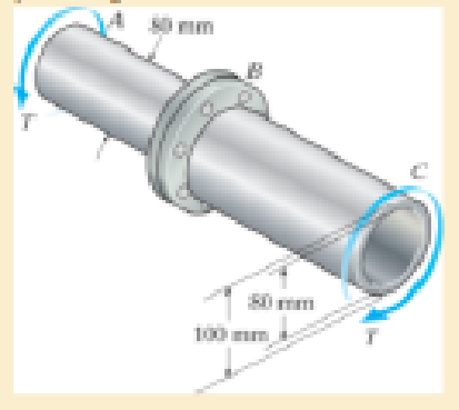
The shaft consists of a solid segment AB and a hollow segment BC, which are rigidly joined by the coupling at B. If the shaft is made from A-36 steel, determine the maximum torque T that can be applied according to the maximum shear stress theory. Use a factor of safety of 1.5 against yielding.
Expert Solution & Answer
Want to see the full answer?
Check out a sample textbook solution
Students have asked these similar questions
The resistance R and load effect S for a given failure mode are statistically independent random variables
with marginal PDF's
1
fR (r) =
0≤r≤100
100'
fs(s)=0.05e-0.05s
(a) Determine the probability of failure by computing the probability content of the failure domain defined
as {r
Please solve this problem as soon as possible My ID# 016948724
The gears shown in the figure have a diametral pitch of 2 teeth per inch and a 20° pressure angle.
The pinion rotates at 1800 rev/min clockwise and transmits 200 hp through the idler pair to gear
5 on shaft c. What forces do gears 3 and 4 transmit to the idler shaft?
TS
I
y
18T
32T
This
a
12
x
18T
C
48T
5
Chapter 10 Solutions
Mechanics of Materials
Ch. 10.3 - Prove that the sum of the normal strains in...Ch. 10.3 - The state of strain at the point on the arm has...Ch. 10.3 - The state of strain at the point on the leaf of...Ch. 10.3 - Use the strain transformation equations and...Ch. 10.3 - Determine the equivalent state of strain on an...Ch. 10.3 - Determine the equivalent state of strain which...Ch. 10.3 - Use the strain transformation equations to...Ch. 10.3 - Determine the equivalent state of strain, which...Ch. 10.3 - Solve Prob.103 using Mohrs circle. 103. The state...Ch. 10.5 - The strain at point A on the bracket has...
Ch. 10.5 - Determine (a) the principal strains at A, (b) the...Ch. 10.6 - For the case of plane stress, show that Hookes law...Ch. 10.6 - to develop the strain tranformation equations....Ch. 10.6 - Determine the associated principal stresses at the...Ch. 10.6 - Determine the applied load P. What is the shear...Ch. 10.6 - If a load of P = 3 kip is applied to the A-36...Ch. 10.7 - A material is subjected to plane stress. Express...Ch. 10.7 - A material is subjected to plane stress. Express...Ch. 10.7 - Solve Prob. 1061 using the maximum distortion...Ch. 10.7 - Solve Prob.1063 using the maximum distortion...Ch. 10.7 - Prob. 70PCh. 10.7 - The plate is made of Tobin bronze, which yields at...Ch. 10.7 - If a machine part is made of titanium (TI-6A1-4V)...Ch. 10.7 - The components of plane stress at a critical point...Ch. 10.7 - If Y = 50 ksi, determine the factor of safety for...Ch. 10.7 - Prob. 82PCh. 10.7 - If the yield stress for steel is Y = 36 ksi,...Ch. 10.7 - Prob. 84PCh. 10.7 - The state of stress acting at a critical point on...Ch. 10.7 - The shaft consists of a solid segment AB and a...Ch. 10 - In the case of plane stress, where the in-plane...Ch. 10 - The plate is made of material having a modulus of...Ch. 10 - If the material is machine steel having a yield...Ch. 10 - Determine if yielding has occurred on the basis of...Ch. 10 - The 60 strain rosette is mounted on a beam. The...Ch. 10 - Use the strain transformation equations to...Ch. 10 - If the strain gages a and b at points give...Ch. 10 - Use the strain-transformation equations and...Ch. 10 - Use the strain transformation equations to...Ch. 10 - Specify the orientation of the corresponding...
Additional Engineering Textbook Solutions
Find more solutions based on key concepts
1.2 Explain the difference between geodetic and plane
surveys,
Elementary Surveying: An Introduction To Geomatics (15th Edition)
17–1C A high-speed aircraft is cruising in still air. How does the temperature of air at the nose of the aircra...
Thermodynamics: An Engineering Approach
How is the hydrodynamic entry length defined for flow in a pipe? Is the entry length longer in laminar or turbu...
Fluid Mechanics: Fundamentals and Applications
Assume a telephone signal travels through a cable at two-thirds the speed of light. How long does it take the s...
Electric Circuits. (11th Edition)
Porter’s competitive forces model: The model is used to provide a general view about the firms, the competitors...
Management Information Systems: Managing The Digital Firm (16th Edition)
What types of coolant are used in vehicles?
Automotive Technology: Principles, Diagnosis, And Service (6th Edition) (halderman Automotive Series)
Knowledge Booster


Learn more about
Need a deep-dive on the concept behind this application? Look no further. Learn more about this topic, mechanical-engineering and related others by exploring similar questions and additional content below.Similar questions
- Question 1. Draw 3 teeth for the following pinion and gear respectively. The teeth should be drawn near the pressure line so that the teeth from the pinion should mesh those of the gear. Drawing scale (1:1). Either a precise hand drawing or CAD drawing is acceptable. Draw all the trajectories of the involute lines and the circles. Specification: 18tooth pinion and 30tooth gear. Diameter pitch=P=6 teeth /inch. Pressure angle:20°, 1/P for addendum (a) and 1.25/P for dedendum (b). For fillet, c=b-a.arrow_forward5. The figure shows a gear train. There is no friction at the bearings except for the gear tooth forces. The material of the milled gears is steel having a Brinell hardness of 170. The input shaft speed (n2) is 800 rpm. The face width and the contact angle for all gears are 1 in and 20° respectively. In this gear set, the endurance limit (Se) is 15 kpsi and nd (design factor) is 2. (a) Find the revolution speed of gear 5. (b) Determine whether each gear satisfies the design factor of 2.0 for bending fatigue. (c) Determine whether each gear satisfies the design factor of 2.0 for surface fatigue (contact stress). (d) According to the computation results of the questions (b) and (c), explain the possible failure mechanisms for each gear. N4=28 800rpm N₁=43 N5=34 N₂=14 P(diameteral pitch)=8 for all gears Coupled to 2.5hp motorarrow_forward1. The rotating steel shaft is simply supported by bearings at points of B and C, and is driven by a spur gear at D, which has a 6-in pitch diameter. The force F from the drive gear acts at a pressure angle of 20°. The shaft transmits a torque to point A of TA =3000 lbĘ in. The shaft is machined from steel with Sy=60kpsi and Sut=80 kpsi. (1) Draw a shear force diagram and a bending moment diagram by F. According to your analysis, where is the point of interest to evaluate the safety factor among A, B, C, and D? Describe the reason. (Hint: To find F, the torque Tд is generated by the tangential force of F (i.e. Ftangential-Fcos20°) When n=2.5, K=1.8, and K₁ =1.3, determine the diameter of the shaft based on (2) static analysis using DE theory (note that fatigue stress concentration factors need to be used for this question because the loading condition is fatigue) and (3) a fatigue analysis using modified Goodman. Note) A standard diameter is not required for the questions. 10 in Darrow_forward
- 3 N2=28 P(diametral pitch)=8 for all gears Coupled to 25 hp motor N3=34 Full depth spur gears with pressure angle=20° N₂=2000 rpm (1) Compute the circular pitch, the center-to-center distance, and base circle radii. (2) Draw the free body diagram of gear 3 and show all the forces and the torque. (3) In mounting gears, the center-to-center distance was reduced by 0.1 inch. Calculate the new values of center-to-center distance, pressure angle, base circle radii, and pitch circle diameters. (4)What is the new tangential and radial forces for gear 3? (5) Under the new center to center distance, is the contact ratio (mc) increasing or decreasing?arrow_forward2. A flat belt drive consists of two 4-ft diameter cast-iron pulleys spaced 16 ft apart. A power of 60 hp is transmitted by a pulley whose speed is 380 rev/min. Use a service factor (Ks) pf 1.1 and a design factor 1.0. The width of the polyamide A-3 belt is 6 in. Use CD=1. Answer the following questions. (1) What is the total length of the belt according to the given geometry? (2) Find the centrifugal force (Fc) applied to the belt. (3) What is the transmitted torque through the pulley system given 60hp? (4) Using the allowable tension, find the force (F₁) on the tight side. What is the tension at the loose side (F2) and the initial tension (F.)? (5) Using the forces, estimate the developed friction coefficient (f) (6) Based on the forces and the given rotational speed, rate the pulley set. In other words, what is the horse power that can be transmitted by the pulley system? (7) To reduce the applied tension on the tight side, the friction coefficient is increased to 0.75. Find out the…arrow_forwardThe tooth numbers for the gear train illustrated are N₂ = 24, N3 = 18, №4 = 30, №6 = 36, and N₁ = 54. Gear 7 is fixed. If shaft b is turned through 5 revolutions, how many turns will shaft a make? a 5 [6] barrow_forward
- Please do not use any AI tools to solve this question. I need a fully manual, step-by-step solution with clear explanations, as if it were done by a human tutor. No AI-generated responses, please.arrow_forwardPlease do not use any AI tools to solve this question. I need a fully manual, step-by-step solution with clear explanations, as if it were done by a human tutor. No AI-generated responses, please.arrow_forwardCE-112 please solve this problem step by step and give me the correct answerarrow_forward
arrow_back_ios
SEE MORE QUESTIONS
arrow_forward_ios
Recommended textbooks for you
 Mechanics of Materials (MindTap Course List)Mechanical EngineeringISBN:9781337093347Author:Barry J. Goodno, James M. GerePublisher:Cengage Learning
 International Edition---engineering Mechanics: St...Mechanical EngineeringISBN:9781305501607Author:Andrew Pytel And Jaan KiusalaasPublisher:CENGAGE L
Mechanics of Materials (MindTap Course List)
Mechanical Engineering
ISBN:9781337093347
Author:Barry J. Goodno, James M. Gere
Publisher:Cengage Learning
International Edition---engineering Mechanics: St...
Mechanical Engineering
ISBN:9781305501607
Author:Andrew Pytel And Jaan Kiusalaas
Publisher:CENGAGE L
Understanding Failure Theories (Tresca, von Mises etc...); Author: The Efficient Engineer;https://www.youtube.com/watch?v=xkbQnBAOFEg;License: Standard youtube license