
Statics and Mechanics of Materials (5th Edition)
5th Edition
ISBN: 9780134382593
Author: Russell C. Hibbeler
Publisher: PEARSON
expand_more
expand_more
format_list_bulleted
Videos
Textbook Question
Chapter 10.3, Problem 1PP
Determine the internal torque at each section and show the shear stress on differential volume elements located at A, B, C, and D.
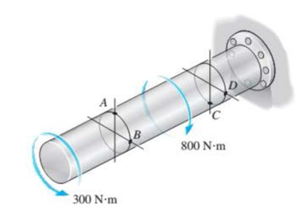
Prob. P10-1
Expert Solution & Answer
Want to see the full answer?
Check out a sample textbook solution
Students have asked these similar questions
Consider the feedback controlled blending system shown below, which is designed to keep theoutlet concentration constant despite potential variations in the stream 1 composition. The density of all streamsis 920 kg/m3. At the nominal steady state, the flow rates of streams 1 and 2 are 950 and 425 kg/min,respectively, the liquid level in the tank is 1.3 m, the incoming mass fractions are x1 = 0.27, x2 = 0.54. Noticethe overflow line, indicating that the liquid level remains constant (i.e. any change in total inlet flow ratetranslates immediately to the same change in the outlet flow rate). You may assume the stream 1 flowrate andthe stream 2 composition are both constant. Use minutes as the time unit throughout this problem.
Identify any controlled variable(s) (CVs), manipulated variable(s) (MVs),and disturbance variable(s) (DVs) in this problem. For each, explain how you know that’show it is classified.CVs: ___________, MVs: _____________, DVs: ______________
b) Draw a block diagram…
A heat transfer experiment is conducted on two identical spheres which are initially at the same
temperature. The spheres are cooled by placing them in a channel. The fluid velocity in the channel is
non-uniform, having a profile as shown. Which sphere cools off more rapidly? Explain.
V
1
My ID# 016948724
last 2 ID# 24
Last 3 ID# 724
Please help to find the correct answer for this problem using my ID# first write le line of action and then help me to find the forces {fx= , fy= mz= and for the last find the moment of inertial about the show x and y axes please show how to solve step by step
Chapter 10 Solutions
Statics and Mechanics of Materials (5th Edition)
Ch. 10.3 - Determine the internal torque at each section and...Ch. 10.3 - Determine the internal torque at each section and...Ch. 10.3 - Prob. 3PPCh. 10.3 - Prob. 4PPCh. 10.3 - Prob. 1FPCh. 10.3 - The hollow circular shaft is subjected to an...Ch. 10.3 - Prob. 3FPCh. 10.3 - Prob. 4FPCh. 10.3 - Determine the maximum shear stress in the shaft at...Ch. 10.3 - Prob. 6FP
Ch. 10.3 - The solid 50-mm-diameter shaft is subjected to the...Ch. 10.3 - Prob. 8FPCh. 10.3 - Prob. 1PCh. 10.3 - Prob. 2PCh. 10.3 - A shaft is made of an aluminum alloy having an...Ch. 10.3 - The copper pipe has an outer diameter of 40 mm and...Ch. 10.3 - The copper pipe has an outer diameter of 2.50 in....Ch. 10.3 - The solid aluminum shaft has a diameter of 50 mm...Ch. 10.3 - The solid aluminum shaft has a diameter of 50 mm....Ch. 10.3 - The solid 30-mm-diameter shaft is used to transmit...Ch. 10.3 - The solid shaft is fixed to the support at C and...Ch. 10.3 - The link acts as part of the elevator control for...Ch. 10.3 - The assembly consists of two sections of...Ch. 10.3 - The shaft has an outer diameter of 100 mm and an...Ch. 10.3 - Prob. 13PCh. 10.3 - Prob. 14PCh. 10.3 - Prob. 15PCh. 10.3 - Prob. 16PCh. 10.3 - The rod has a diameter of 1 in. and a weight of 10...Ch. 10.3 - Prob. 18PCh. 10.3 - Prob. 19PCh. 10.3 - Prob. 20PCh. 10.3 - Prob. 21PCh. 10.3 - The 60-mm-diametcr solid shaft is subjected to the...Ch. 10.3 - Prob. 23PCh. 10.3 - The 60-mm-diameter solid shaft is subjected to the...Ch. 10.3 - Prob. 25PCh. 10.3 - The pump operates using the motor that has a power...Ch. 10.3 - Prob. 27PCh. 10.3 - Prob. 28PCh. 10.3 - Prob. 29PCh. 10.3 - The gear motor can develop 2 hp when it turns at...Ch. 10.3 - Prob. 31PCh. 10.3 - The 6-hp reducer motor can turn at 1200 rev/min....Ch. 10.3 - Prob. 33PCh. 10.3 - Prob. 34PCh. 10.4 - The 60-mm-diameter steel shaft is subjected to the...Ch. 10.4 - Prob. 10FPCh. 10.4 - The hollow 6061-T6 aluminum shaft has an outer and...Ch. 10.4 - A series of gears are mounted on the...Ch. 10.4 - Prob. 13FPCh. 10.4 - The 80-mm-diameter shaft is made of steel. If it...Ch. 10.4 - The propellers of a ship are connected to an A-36...Ch. 10.4 - Prob. 36PCh. 10.4 - The splined ends and gears attached to the A992...Ch. 10.4 - Prob. 38PCh. 10.4 - The 60-mm-diameter shaft is made of 6061-T6...Ch. 10.4 - The 60-mm-diameter shaft is made of 6061-T6...Ch. 10.4 - Prob. 41PCh. 10.4 - Prob. 42PCh. 10.4 - Gear B supplies 15 kW of power, while gears A, C,...Ch. 10.4 - Prob. 44PCh. 10.4 - The turbine develops 150 kW of power, which is...Ch. 10.4 - Prob. 46PCh. 10.4 - Prob. 47PCh. 10.4 - Prob. 48PCh. 10.4 - The A 992 steel shaft has a diameter of 50 mm and...Ch. 10.4 - The turbine develops 300 kW of power, which is...Ch. 10.4 - Prob. 51PCh. 10.4 - The device shown is used to mix soils in order to...Ch. 10.4 - The 6-in.-diameter L-2 steel shaft on the turbine...Ch. 10.4 - The A-36 hollow steel shaft is 2 m long and has an...Ch. 10.4 - The A-36 solid steel shaft is 3 m long and has a...Ch. 10.4 - Prob. 56PCh. 10.4 - Prob. 57PCh. 10.4 - Prob. 58PCh. 10.4 - The tubular drive shaft for the propeller of a...Ch. 10.4 - The 60-mm diameter solid shaft is made of 2014-T6...Ch. 10.4 - Prob. 61PCh. 10.5 - The steel shaft has a diameter of 40 mm and is...Ch. 10.5 - The A992 steel shaft has a diameter of 60 mm and...Ch. 10.5 - The steel shaft is made from two segments: AC has...Ch. 10.5 - The bronze C86100 pipe has an outer diameter of...Ch. 10.5 - The bronze C86100 pipe has an outer diameter of...Ch. 10.5 - Prob. 67PCh. 10.5 - Prob. 68PCh. 10.5 - The Am1004-T61 magnesium tube is bonded to the...Ch. 10.5 - The Am1004-T61 magnesium tube is bonded to the...Ch. 10.5 - The two shafts are made of A-36 steel. Each has a...Ch. 10.5 - Prob. 72PCh. 10.5 - Prob. 73PCh. 10.5 - Prob. 74PCh. 10.5 - Prob. 75PCh. 10.5 - The composite shaft consists of a mid-section that...Ch. 10.5 - Prob. 77PCh. 10.5 - The tapered shaft is confined by the fixed...Ch. 10.5 - Prob. 79PCh. 10 - The shaft is made of A992 steel and has an...Ch. 10 - The shaft is made of A992 steel and has an...Ch. 10 - The A-36 steel circular tube is subjected to a...Ch. 10 - Prob. 4RPCh. 10 - Prob. 5RPCh. 10 - Prob. 6RPCh. 10 - Prob. 7RPCh. 10 - Prob. 8RPCh. 10 - The 60-mm-diameter shaft rotates at 300 rev/min....
Knowledge Booster


Learn more about
Need a deep-dive on the concept behind this application? Look no further. Learn more about this topic, mechanical-engineering and related others by exploring similar questions and additional content below.Similar questions
- My ID# 016948724 last 2 ID# 24 Last 3 ID# 724 Please help to find the correct answer for this problem using my ID# first write le line of action and then help me to find the forces and the tension {fx= , fy= mz=arrow_forwardMy ID# 016948724 last 2 ID# 24 Last 3 ID# 724 Please help to find the correct answer for this problem using my ID# first write le line of action and then help me to find the forces {fx= , fy= mz=arrow_forwardmy ID is 016948724 Last 2 ID# 24 Last 3 ID# 724 please help me to solve this problem step by step show me how to solve first wirte the line actions and then find the forces {fx=, fy=, mz= and for the last step find the support reactions and find forcesarrow_forward
- Uppgift 1 (9p) 3 m 3 m 3 m 3 m H G F 3 m ↑ Dy D B AAY 30° 8 kN Ay Fackverket i figuren ovan är belastat med en punktlast. Bestäm normalkraften i stängerna BC, BG och FG.arrow_forwardThe cardiovascular countercurrent heat exchnager mechanism is to warm venous blood from 28 degrees C to 35 degrees C at a mass flow rate of 2 g/s. The artery inflow temp is 37 degrees C at a mass flow rate of 5 g/s. The average diameter of the vein is 5 cm and the overall heat transfer coefficient is 125 W/m^2*K. Determine the overall blood vessel length needed too warm the venous blood to 35 degrees C if the specific heat of both arterial and venous blood is constant and equal to 3475 J/kg*K.arrow_forwardThe forces Qy=12 kNQy=12kN and Qz=16 kNQz=16kN act on the profile at the shear center C. Calculate: a) Shear flow at point B (2 points)b) Shear stress at point D (3 points)arrow_forward
- Consider the feedback controlled blending system shown below, which is designed to keep theoutlet concentration constant despite potential variations in the stream 1 composition. The density of all streamsis 920 kg/m3. At the nominal steady state, the flow rates of streams 1 and 2 are 950 and 425 kg/min,respectively, the liquid level in the tank is 1.3 m, the incoming mass fractions are x1 = 0.27, x2 = 0.54. Noticethe overflow line, indicating that the liquid level remains constant (i.e. any change in total inlet flow ratetranslates immediately to the same change in the outlet flow rate). You may assume the stream 1 flowrate andthe stream 2 composition are both constant. Use minutes as the time unit throughout this problem. d) Derive the first order process and disturbance transfer functions;Gp= Kp/(tou*s+1) and Gd=Kd/(tou*s+1) and calculate and list the values and units of the parameters. e) Using the given information, write the general forms of Gm, GIP, and Gv below(in terms of…arrow_forwarda) Briefly explain what ratio control is. Give an example of a common chemical engineering situation in whichratio control would be useful and for that example state exactly how ratio control works (what would bemeasured, what is set, and how the controller logic works).b) Briefly explain what cascade control is. Give an example of a common chemical engineering situation inwhich cascade control would be useful and for that example state exactly how cascade control works (whatwould be measured, what is set, and how the controller logic works).arrow_forwardDetermine the reaction force acting on the beam AB, given F = 680 N. 5 4 4 m 3 3 A B 30° 3 m F (N)arrow_forward
- The frame in the figure is made of an HEA 300 profile (E = 210 GPa, material S355).a) Determine the support reactions at point A. (1p)b) Sketch the bending moment diagram caused by the loading. (1p)c) Using the principle of virtual work (unit load method), calculate the vertical displacement at point B using moment diagrams. Also take into account the compression of the column. (3p)arrow_forward9 kN/m 6 kN/m 3 m 6 m Bestäm, med hjälp av friläggning och jämviktsberäkningar, tvärkrafts- och momentdiagram för balken i figuren. Extrempunkter ska anges med både läge och värde.arrow_forwardB C 3.0 E F G 40 kN [m] 3.0 3.0 3.0 Fackverket belastas med en punktlast i G enligt figuren. Bestäm normalkraften i stängerna BC, BF och EF.arrow_forward
arrow_back_ios
SEE MORE QUESTIONS
arrow_forward_ios
Recommended textbooks for you
 Elements Of ElectromagneticsMechanical EngineeringISBN:9780190698614Author:Sadiku, Matthew N. O.Publisher:Oxford University Press
 Mechanics of Materials (10th Edition)Mechanical EngineeringISBN:9780134319650Author:Russell C. HibbelerPublisher:PEARSON
 Thermodynamics: An Engineering ApproachMechanical EngineeringISBN:9781259822674Author:Yunus A. Cengel Dr., Michael A. BolesPublisher:McGraw-Hill Education
 Control Systems EngineeringMechanical EngineeringISBN:9781118170519Author:Norman S. NisePublisher:WILEY
 Mechanics of Materials (MindTap Course List)Mechanical EngineeringISBN:9781337093347Author:Barry J. Goodno, James M. GerePublisher:Cengage Learning
 Engineering Mechanics: StaticsMechanical EngineeringISBN:9781118807330Author:James L. Meriam, L. G. Kraige, J. N. BoltonPublisher:WILEY
Elements Of Electromagnetics
Mechanical Engineering
ISBN:9780190698614
Author:Sadiku, Matthew N. O.
Publisher:Oxford University Press
Mechanics of Materials (10th Edition)
Mechanical Engineering
ISBN:9780134319650
Author:Russell C. Hibbeler
Publisher:PEARSON
Thermodynamics: An Engineering Approach
Mechanical Engineering
ISBN:9781259822674
Author:Yunus A. Cengel Dr., Michael A. Boles
Publisher:McGraw-Hill Education
Control Systems Engineering
Mechanical Engineering
ISBN:9781118170519
Author:Norman S. Nise
Publisher:WILEY
Mechanics of Materials (MindTap Course List)
Mechanical Engineering
ISBN:9781337093347
Author:Barry J. Goodno, James M. Gere
Publisher:Cengage Learning
Engineering Mechanics: Statics
Mechanical Engineering
ISBN:9781118807330
Author:James L. Meriam, L. G. Kraige, J. N. Bolton
Publisher:WILEY
BEARINGS BASICS and Bearing Life for Mechanical Design in 10 Minutes!; Author: Less Boring Lectures;https://www.youtube.com/watch?v=aU4CVZo3wgk;License: Standard Youtube License