
ENGINEERING CIRCUIT...(LL)>CUSTOM PKG.<
9th Edition
ISBN: 9781260540666
Author: Hayt
Publisher: MCG CUSTOM
expand_more
expand_more
format_list_bulleted
Videos
Textbook Question
Chapter 10, Problem 76E
For the circuit shown in Fig. 10.79, (a) draw the phasor representation of the circuit; (b) determine the Thévenin equivalent seen by the capacitor, and use it to calculate vC(t). (c) Determine the current flowing out of the positive reference terminal of the voltage source. (d) Verify your solution with an appropriate LTspice simulation.
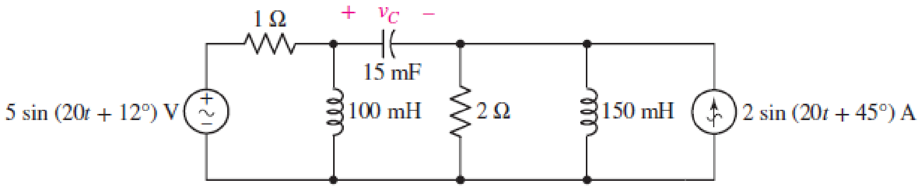
■ FIGURE 10.79
Expert Solution & Answer
Want to see the full answer?
Check out a sample textbook solution
Students have asked these similar questions
Describe how you would choose the input and output capacitors for a common source amplifier.
Whats the difference between an common-source and a common-drain amplifier (gain, input/output impedance)?
can you asnwer
Chapter 10 Solutions
ENGINEERING CIRCUIT...(LL)>CUSTOM PKG.<
Ch. 10.1 - Find the angle by which i1 lags v1 if v1 = 120...Ch. 10.2 - Determine values for A, B, C, and if 40 cos(100t ...Ch. 10.2 - Let vs = 40 cos 8000t V in the circuit of Fig....Ch. 10.3 - Prob. 4PCh. 10.3 - If the use of the passive sign convention is...Ch. 10.4 - Let = 2000 rad/s and t = 1 ms. Find the...Ch. 10.4 - Transform each of the following functions of time...Ch. 10.4 - In the circuit of Fig. 10.17, both sources operate...Ch. 10.5 - With reference to the network shown in Fig. 10.19,...Ch. 10.5 - In the frequency-domain circuit of Fig. 10.21,...
Ch. 10.5 - Determine the admittance (in rectangular form) of...Ch. 10.6 - Use nodal analysis on the circuit of Fig. 10.23 to...Ch. 10.6 - Use mesh analysis on the circuit of Fig. 10.25 to...Ch. 10.7 - If superposition is used on the circuit of Fig....Ch. 10.7 - Prob. 15PCh. 10.7 - Determine the current i through the 4 resistor of...Ch. 10.8 - Select some convenient reference value for IC in...Ch. 10 - Evaluate the following: (a) 5 sin (5t 9) at t =...Ch. 10 - (a) Express each of the following as a single...Ch. 10 - Prob. 3ECh. 10 - Prob. 4ECh. 10 - Prob. 5ECh. 10 - Calculate the first three instants in time (t 0)...Ch. 10 - (a) Determine the first two instants in time (t ...Ch. 10 - The concept of Fourier series is a powerful means...Ch. 10 - Household electrical voltages are typically quoted...Ch. 10 - Prob. 10ECh. 10 - Assuming there are no longer any transients...Ch. 10 - Calculate the power dissipated in the 2 resistor...Ch. 10 - Prob. 13ECh. 10 - Prob. 14ECh. 10 - Prob. 15ECh. 10 - Express the following complex numbers in...Ch. 10 - Prob. 17ECh. 10 - Prob. 18ECh. 10 - Evaluate the following, and express your answer in...Ch. 10 - Perform the indicated operations, and express the...Ch. 10 - Insert an appropriate complex source into the...Ch. 10 - For the circuit of Fig. 10.51, if is = 2 cos 5t A,...Ch. 10 - In the circuit depicted in Fig. 10.51, if is is...Ch. 10 - Employ a suitable complex source to determine the...Ch. 10 - Transform each of the following into phasor form:...Ch. 10 - Prob. 26ECh. 10 - Prob. 27ECh. 10 - The following complex voltages are written in a...Ch. 10 - Assuming an operating frequency of 50 Hz, compute...Ch. 10 - Prob. 30ECh. 10 - Prob. 31ECh. 10 - Prob. 32ECh. 10 - Assuming the passive sign convention and an...Ch. 10 - The circuit of Fig. 10.53 is shown represented in...Ch. 10 - (a) Obtain an expression for the equivalent...Ch. 10 - Determine the equivalent impedance of the...Ch. 10 - (a) Obtain an expression for the equivalent...Ch. 10 - Determine the equivalent admittance of the...Ch. 10 - Prob. 40ECh. 10 - Prob. 41ECh. 10 - Find V in Fig. 10.55 if the box contains (a) 3 in...Ch. 10 - Prob. 43ECh. 10 - Prob. 44ECh. 10 - Design a suitable combination of resistors,...Ch. 10 - Design a suitable combination of resistors,...Ch. 10 - For the circuit depicted in Fig. 10.58, (a) redraw...Ch. 10 - For the circuit illustrated in Fig. 10.59, (a)...Ch. 10 - Referring to the circuit of Fig. 10.59, employ...Ch. 10 - In the phasor-domain circuit represented by Fig....Ch. 10 - With regard to the two-mesh phasor-domain circuit...Ch. 10 - Employ phasor analysis techniques to obtain...Ch. 10 - Determine IB in the circuit of Fig. 10.62 if and ....Ch. 10 - Determine V2 in the circuit of Fig. 10.62 if and ....Ch. 10 - Employ phasor analysis to obtain an expression for...Ch. 10 - Determine the current ix in the circuit of Fig....Ch. 10 - Obtain an expression for each of the four...Ch. 10 - Determine the nodal voltages for the circuit of...Ch. 10 - Prob. 59ECh. 10 - Obtain an expression for each of the four mesh...Ch. 10 - Determine the individual contribution each current...Ch. 10 - Determine V1 and V2 in Fig. 10.68 if I1 = 333 mA...Ch. 10 - Prob. 63ECh. 10 - Obtain the Thvenin equivalent seen by the (2 j) ...Ch. 10 - The (2 j) impedance in the circuit of Fig. 10.69...Ch. 10 - With regard to the circuit depicted in Fig. 10.70,...Ch. 10 - Prob. 67ECh. 10 - Determine the individual contribution of each...Ch. 10 - Determine the power dissipated by the 1 resistor...Ch. 10 - The source Is in the circuit of Fig. 10.75 is...Ch. 10 - Prob. 72ECh. 10 - (a) Calculate values for IL, IR, IC, VL, VR, and...Ch. 10 - In the circuit of Fig. 10.77, (a) find values for...Ch. 10 - The voltage source Vs in Fig. 10.78 is chosen such...Ch. 10 - For the circuit shown in Fig. 10.79, (a) draw the...Ch. 10 - For the circuit shown in Fig. 10.80, (a) draw the...Ch. 10 - (a) Replace the inductor in the circuit of Fig....Ch. 10 - Design a purely passive network (containing only...
Knowledge Booster


Learn more about
Need a deep-dive on the concept behind this application? Look no further. Learn more about this topic, electrical-engineering and related others by exploring similar questions and additional content below.Similar questions
- can you please answerarrow_forwardcan you please answerarrow_forwardThe line diagram is of a standard forward/reverse/stop pushbutton station for forwarding and reversing a motor. Included in the circuit are mechanical and auxiliary contact interlocking. Also included are a forward overtravel limit switch to stop the motor in forward and a reverse overtravel limit switch to stop the motor in reverse. Overload protection is common to both forward and reverse directions. Complete the wiring diagram based on the line diagram. Do not make any wire splices or additional terminal connections on the wiring diagram (notice how they make multiple connections in the power circuit). All connections must run from terminal screw to terminal screw complete the wiring diagram based on the line diagram. Do not make any wires splices or additional terminal connections on the wiring diagram. All connections must run from terminal screw to terminal screwarrow_forward
- 6.7 Consider a baseband binary PAM system that transmits at 3600 bps with a bit error rate less than 10-4. The channel introduces no distortion, but attenuates the signal by 20 dB and has a bandwidth of 2.4 kHz. The channel noise is AWGN with a power spectral density of 10-14 watts per Hertz (W/Hz). Design the optimum transmitting and receiving filters, and determine the required transmit power.arrow_forward6.10 In a baseband digital transmission, the bandwidth is 4 kHz, and the bit rate must be at least 38.4 kbps. Assuming M-ary signaling, determine the range of acceptable values of M, and the resulting bit error rate.arrow_forwardAssume a JFET device with VGS(0) = -1.3 and ipss = 20 mA. Design a self-biased (Fig. 2) JFET common-source amplifier with the gain of -2 and a DC biasing that allows the largest swing in ip. Note that you can choose Vcc to arrive at a desired RD to meet the gain requirement. Since you are designing for a given gain, you may have to check to see if JFET is biased correctly. (Hint: First find Rs for correct VGs and then use the gain to compute RD. Finally, use RD and Rs to determine Vec). Assume that the amplifier is to interface a source that expects a load of 50 2. Also, assume that the amplifier circuit is AC coupled at both ends with 3 dB corner frequency of 15 kHz.arrow_forward
- EXAMPLE 6.7 Consider an M-ary system with the number of symbols M=16, and the roll-off factor a= Discuss this M-ary system, vis-à-vis the corresponding binary system, for various scenarios. Solution 1arrow_forwardDesign an oscillator circuit using the arrangement in Fig. 4 (namely, find C+1=C+2). Fig. 4 shows that we are using a pair of 2N5485 JFET. However, you are supplied with two J112 (or J113) to be used here. Use datasheet for J112 (or J113) to determine the needed capacitances. The oscillation frequency is considered to be 1 MHz. Use L₁ = L₂ = 112 μH. Furthermore, assume Cr=200 pF and Re = 300 . Is the assumption Cf >> CGS&CGD valid?arrow_forward10pts: Matlab: From Problem 1 of homework 6, repeated below: Generate a random binary PAM transmit signal of -1 and + 1 volts of length 100. Simulate the transmit signal being sent over a channel with AWGN with an Eb/No of 3 dB. Plot the received signal constellation using a red o to represent when a logical 0 was sent and a blue * to represent a logical 1 was sent Question (1) Increase the Eb/No to 7 dB. Approximately what length of the signal do you need to get consistently within ~5% of the theoretical value for the bit error rate? a) Guess without doing any simulations b) Estimate by trial and observing the results.arrow_forward
- (1) A baseband PAM communication channel bandwidth is 100 KHz and has a noise power spectral density of 10^-9 W/Hz. The channel loss between the transmitter and receiver is 25dB. The application requires a bit rate of 500 Kbps and BER of less than 10^-5. The system uses raised cosine pulses with a roll-off factor of 0.25. Determine the minimum transmit power required. (2) Continuing problem 1. Everything for the previous problem stays the same BUT the best Power Amplifier you can afford has a maximum output power of 10 Watts. What will be estimated BER for the system?arrow_forwardExplain magnetic hysteresis and give examples of some calculationsarrow_forwardEXAMPLE 6.8 Suppose the samples of the nonideal received pulse are as follows: 0. m1 Design a three-tap ZF equalizer.arrow_forward
arrow_back_ios
SEE MORE QUESTIONS
arrow_forward_ios
Recommended textbooks for you
 Delmar's Standard Textbook Of ElectricityElectrical EngineeringISBN:9781337900348Author:Stephen L. HermanPublisher:Cengage Learning
Delmar's Standard Textbook Of Electricity
Electrical Engineering
ISBN:9781337900348
Author:Stephen L. Herman
Publisher:Cengage Learning
Routh Hurwitz Stability Criterion Basic Worked Example; Author: The Complete Guide to Everything;https://www.youtube.com/watch?v=CzzsR5FT-8U;License: Standard Youtube License