
Delmar's Standard Textbook of Electricity (MindTap Course List)
6th Edition
ISBN: 9781285852706
Author: Stephen L. Herman
Publisher: Cengage Learning
expand_more
expand_more
format_list_bulleted
Concept explainers
Videos
Textbook Question
Chapter 10, Problem 2PP
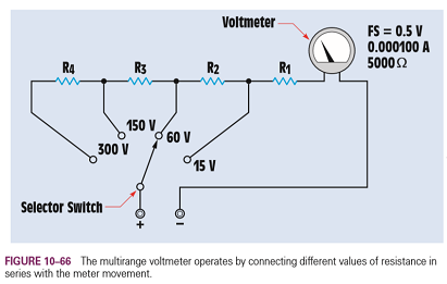
The meter movement described in Question 1 is to be used to construct a multi-range voltmeter. The meter is to have voltage ranges of 15 V, 60 V, 150 V, and 300 V (Figure 10- 66). Find the values of R1, R2, R3, and R4.
Expert Solution & Answer
Want to see the full answer?
Check out a sample textbook solution
Students have asked these similar questions
B. For the oscillator circuit shown in
frequency, feedback and open-loop gains.
+10 V
name the circuit, derive and find the oscillation
P.Av
+9 V
-000
4₁
5 mH
w
R₁
C₂
HH
1 με
w
100 pF
R₂
T
R
CA
www.
470 pF
w
ww
www
1000 pF
HH
1μF
C₁
HH
1μF
Ra
ww
HI
4₁
000
1.5 mH
H
4
AF
000
10 mH
I want to check if the current that I have from using the mesh analysis is correct?
I1 = 0.214mA
I2 = -0.429mA
I want to find the current by using mesh analysis please
Chapter 10 Solutions
Delmar's Standard Textbook of Electricity (MindTap Course List)
Ch. 10 - To what is the turning force of a dArsonval meter...Ch. 10 - Prob. 2RQCh. 10 - A DC voltmeter has a resistance of 20,000 per...Ch. 10 - 4. What is the purpose of an ammeter shunt?
Ch. 10 - 5. Name two methods used to make a DC multirange...Ch. 10 - 6. How is an ammeter connected into a circuit?
Ch. 10 - 7. How is a voltmeter connected into a circuit?
Ch. 10 - 8. An ammeter shunt has a voltage drop of 50 mV...Ch. 10 - 9. What type of meter contains its own separate...Ch. 10 - 10. What electrical quantity does the oscilloscope...
Ch. 10 - 11. What is measured on the Y axis of an...Ch. 10 - 12. What is measured on the X axis of an...Ch. 10 - 13. A waveform shown on the display of an...Ch. 10 - 14. What is the major difference between a...Ch. 10 - 15. What two factors determine the turning force...Ch. 10 - You are an electrician on the job. You have been...Ch. 10 - 1. A d'Arsonval meter movement has a full-scale...Ch. 10 - The meter movement described in Question 1 is to...Ch. 10 - 3. A meter movement has a full-scale value of . A...Ch. 10 - The meter movement described in Question 1 is to...Ch. 10 - 5. A digital voltmeter indicates a voltage of 2.5...
Knowledge Booster


Learn more about
Need a deep-dive on the concept behind this application? Look no further. Learn more about this topic, electrical-engineering and related others by exploring similar questions and additional content below.Similar questions
- I want to find the current by using mesh analysis pleasearrow_forwardR₁ W +10 V R3 +9 V C₂ R₁ CA C₁ 470 pF HH 1000 pF HH 1 με C4 1 μF 1 uF C₁ R₂ R4 100 pF Find Open-loop Jain L₁ 5 mH (a) Av=S,B={" H R₁₂ ✓ ww (b) R₁ L₁ 000 1.5 mH R₂ H 1 uF 12 10 mHarrow_forwardA) Calculate the efficiency of the test transformer at the resistive loads (X-25%, 50%, 75%, 100%, 125% full load). B) From part (A) draw the plot (efficiency Vs power output) of the transformer. C) Discuss the plot of part (B).arrow_forward
- a- Determine fH; and Ho b- Find fg and fr. c- Sketch the frequency response for the high-frequency region using a Bode plot and determine the cutoff frequency. Ans: 277.89 KHz; 2.73 MHz; 895.56 KHz; 107.47 MHz. 14V Cw=5pF Cwo-8pF Coc-12 pF 5.6kQ Ch. 40. pF C-8pF 68kQ 0.47µF Vo 0.82 kQ V₁ B=120 0.47µF www 3.3kQ 10kQ 1.2kQ =20µF Narrow_forwardUsing D flip-flops, design a synchronous counter. The counter counts in the sequence 1,3,5,7, 1,7,5,3,1,3,5,7,.... when its enable input x is equal to 1; otherwise, the counter. This counter is for individual settings only need the state diagram and need the state table to use 16 states from So to S15.arrow_forward: A sequential network has one input (X) and two outputs (Z1 and Z2). An output Z1 Z2 = 10 occurs every time the input sequence 1011 is completed. An output Z1 Z2 = 01 occurs every time the input sequence 0101 is completed. Otherwise Z1 Z2 = 0 Find Moore state diagram with minimum number of states: a) When overlap is allowed. b) When overlap is not allowed. I need a step by step printable solution that uses sequences on the same drawing.arrow_forward
- 1. Consider a negative unity-feedback control system whose plant transfer function is type- 1. Suppose you want to build a lead compensator so that -3 ± 5j are dominant poles. You observed that the angle deficiency at the desired dominant pole is 50°. Compute a 's+b' and b of the lead compensator (s+ 2) so that the error constant Ky is maximized. In other words, design the lead compensator in a way so that the steady-state error for ramp input is minimumarrow_forwardEXAMPLE 8.12 The E-MOSFET of Fig. 8.40 was analyzed in Example 7.10, with the result that k = 0.24 × 10³ A/V², VGS = 6.4 V, and ID = 2.75 mA. a. Determine gm- b. Find rd. c. Calculate Z; with and without rd. Compare results. d. Find Zo with and without ra. Compare results. e. Find A, with and without rd. Compare results. 카 1 uF Z RE 912 V Rp • 2 ΚΩ 10 ΜΩ HE 1 μF ID (on) = 6 mA VGS (on) = 8 V VGS (Th) = 3 V 80s = 20 μs Za o Voarrow_forwardNO AI PLEASEarrow_forward
- NO AI PLEASEarrow_forwardI need handwritten solution to this, electrical engineering expert tutor s only,this is an assignment,I need 100% accuracyarrow_forward5. Determine the CT convolutions for the signals below. Sketch the signal that flips and on same plot the one that is not flipped. Do this for each overlap case. Clearly indicate all overlap cases and the integral limits. Finally, using the left squiggly bracket notation, show the output for each case versus time. (c) 4 x(t) 2 1 2(t) 4 x(t) 4 0123 et 20 x(t) (4) 4 (a) +(1) 24 T 0123 (b) T (f) 1 2-2 0123 (c) (f) 0123 (d) (1) A t 1(8) 4,121 -101 3 (e)arrow_forward
arrow_back_ios
SEE MORE QUESTIONS
arrow_forward_ios
Recommended textbooks for you
 Delmar's Standard Textbook Of ElectricityElectrical EngineeringISBN:9781337900348Author:Stephen L. HermanPublisher:Cengage Learning
 Electricity for Refrigeration, Heating, and Air C...Mechanical EngineeringISBN:9781337399128Author:Russell E. SmithPublisher:Cengage Learning
Delmar's Standard Textbook Of Electricity
Electrical Engineering
ISBN:9781337900348
Author:Stephen L. Herman
Publisher:Cengage Learning
Electricity for Refrigeration, Heating, and Air C...
Mechanical Engineering
ISBN:9781337399128
Author:Russell E. Smith
Publisher:Cengage Learning
Electrical Measuring Instruments - Testing Equipment Electrical - Types of Electrical Meters; Author: Learning Engineering;https://www.youtube.com/watch?v=gkeJzRrwe5k;License: Standard YouTube License, CC-BY
01 - Instantaneous Power in AC Circuit Analysis (Electrical Engineering); Author: Math and Science;https://www.youtube.com/watch?v=If25y4Nhvw4;License: Standard YouTube License, CC-BY