
Electronics Fundamentals: Circuits, Devices & Applications
8th Edition
ISBN: 9780135072950
Author: Thomas L. Floyd, David Buchla
Publisher: Prentice Hall
expand_more
expand_more
format_list_bulleted
Videos
Textbook Question
Chapter 10, Problem 25P
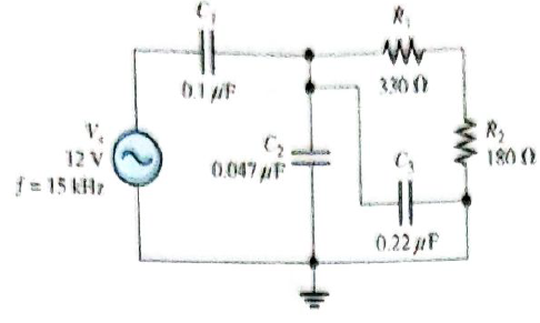
Find the current through each branch and the total current in Figure 10-82.
Expert Solution & Answer
Want to see the full answer?
Check out a sample textbook solution
Students have asked these similar questions
Find Va and Vb using mesh analysis
Find Va and Vb using Mesh analysis
Find Va and Vb using nodal analysis
Chapter 10 Solutions
Electronics Fundamentals: Circuits, Devices & Applications
Ch. 10 - In a series RC circuit, the impedance increases...Ch. 10 - In a series RC lag circuit, the output voltage is...Ch. 10 - Admittance is the reciprocal of susceptance.Ch. 10 - In a parallel RC circuit, as frequency is...Ch. 10 - The phase angle of an RC circuit is measured...Ch. 10 - Prob. 6TFQCh. 10 - Prob. 7TFQCh. 10 - The power factor is equal to the tangent of the...Ch. 10 - A purely resistive circuit has a power factor of...Ch. 10 - Prob. 10TFQ
Ch. 10 - Prob. 1STCh. 10 - Prob. 2STCh. 10 - Prob. 3STCh. 10 - When the frequency of the voltage applied to a...Ch. 10 - Prob. 5STCh. 10 - Prob. 6STCh. 10 - The voltages in Problem 6 are measured at a...Ch. 10 - Prob. 8STCh. 10 - Prob. 9STCh. 10 - When the frequency of the source voltage is...Ch. 10 - Prob. 11STCh. 10 - Prob. 12STCh. 10 - Prob. 13STCh. 10 - Prob. 14STCh. 10 - If the bandwidth or a certain low-pass filter is 1...Ch. 10 - Prob. 1TSCCh. 10 - Prob. 2TSCCh. 10 - Prob. 3TSCCh. 10 - Determine the cause for each set of symptoms....Ch. 10 - Determine the cause for each set of symptoms....Ch. 10 - An 8 kHz sinusoidal voltage is applied to a series...Ch. 10 - What is th waveshape of the current in the circuit...Ch. 10 - Find the impedance of each circuit in Figure...Ch. 10 - Determine the impedance and the phase angle in...Ch. 10 - For the circuit of Figure 10-69, determine the...Ch. 10 - Repeat Problem 5 for C=0.0047F.Ch. 10 - Calculate the total current in each circuit of...Ch. 10 - Repeat Problem 7 for the circuits in Figure 10-68.Ch. 10 - For the circuit in Figure 10-70, draw the phase or...Ch. 10 - For the circuit in Figure 10-71, determine the...Ch. 10 - To what value must the rheostat be set in Figure...Ch. 10 - For the lag circuit in Figure 10-73, determine the...Ch. 10 - Repeat Problem 12 for the lead circuit in Figure...Ch. 10 - Determine the impedance for the circuit in Figure...Ch. 10 - Determine the impedance and the phase angle in...Ch. 10 - Repeat Problem 15 for the following frequencies:...Ch. 10 - Determine the impedance and phase angle in Figure...Ch. 10 - For the circuit in Figure 10-78, find all the...Ch. 10 - For the parallel circuit in Figure 10-79, find...Ch. 10 - For the circuit in Figu 10-80, determine the...Ch. 10 - Repeat Problem 20forR=4.7k,C=0.047F,andf=500Hz.Ch. 10 - Convert the circuit in Figure 10-81 to an...Ch. 10 - Determine the voltages across each element in...Ch. 10 - Is the circuit in Figure 10-82 predominantly...Ch. 10 - Find the current through each branch and the total...Ch. 10 - For the circuit in Figure 10-83, determine the...Ch. 10 - In a certain seris RC circuit, the true power is 2...Ch. 10 - In Figure 10-71, what is the true power and the...Ch. 10 - What is the power factor for the circuit of Figure...Ch. 10 - Determine Ptrue, Pr, Pa,andPF for the circuit in...Ch. 10 - The lag circuit in Figure 10-73 also acts as a...Ch. 10 - Plot the frequency response curve for the circuit...Ch. 10 - Draw the voltage phasor diagram for each circuit...Ch. 10 - Thr rms value of the signal voltage out of...Ch. 10 - Determine the cutoff frequency for each circuit in...Ch. 10 - Determine the bandwidth of the circuit in Figure...Ch. 10 - Assume that the capacitor in Figure 10-85 is...Ch. 10 - Each of the capacitors in Figure 10-86 has...Ch. 10 - Determine the output voltage for the circuit in...Ch. 10 - Determine the output voltage for the circuit in...Ch. 10 - A single 240V,60Hz source drives two loads. Load A...Ch. 10 - What value of coupling capacitor is required in...Ch. 10 - Determine the value of R1 required to get a phase...Ch. 10 - Draw the voltage and current phasor diagram for...Ch. 10 - A certain load dissipates 1.5kW of power with an...Ch. 10 - Deteine the series element or element that are in...Ch. 10 - Determine the value of C2 in Figure 10-91 when...Ch. 10 - Draw the schematic for the circuit in Figure 10-92...Ch. 10 - Open file P10-49; files are found at...Ch. 10 - Open file P10-50. Determine if there is a fault...Ch. 10 - www.prenhall.com/floyd. Open file P10-51....Ch. 10 - www.prenhall.com/floyd. Open file P10-52....Ch. 10 - www.prenhall.com/floyd. Open file P10-53....Ch. 10 - www.prenhall.com/floyd. Open file P10-54....
Knowledge Booster


Learn more about
Need a deep-dive on the concept behind this application? Look no further. Learn more about this topic, electrical-engineering and related others by exploring similar questions and additional content below.Similar questions
- 2. Using the approximate method, hand sketch the Bode plot for the following transfer functions. a) H(s) = 10 b) H(s) (s+1) c) H(s): = 1 = +1 100 1000 (s+1) 10(s+1) d) H(s) = (s+100) (180+1)arrow_forwardQ4: Write VHDL code to implement the finite-state machine described by the state Diagram in Fig. 1. Fig. 1arrow_forward1. Consider the following feedback system. Bode plot of G(s) is shown below. Phase (deg) Magnitude (dB) -50 -100 -150 -200 0 -90 -180 -270 101 System: sys Frequency (rad/s): 0.117 Magnitude (dB): -74 10° K G(s) Bode Diagram System: sys Frequency (rad/s): 36.8 Magnitude (dB): -99.7 System: sys Frequency (rad/s): 20 Magnitude (dB): -89.9 System: sys Frequency (rad/s): 20 Phase (deg): -143 System: sys Frequency (rad/s): 36.8 Phase (deg): -180 101 Frequency (rad/s) a) Determine the range of K for which the closed-loop system is stable. 102 10³ b) If we want the gain margin to be exactly 50 dB, what is value for K we should choose? c) If we want the phase margin to be exactly 37°, what is value of K we should choose? What will be the corresponding rise time (T) for step-input? d) If we want steady-state error of step input to be 0.6, what is value of K we should choose?arrow_forward
- : Write VHDL code to implement the finite-state machine/described by the state Diagram in Fig. 4. X=1 X=0 solo X=1 X=0 $1/1 X=0 X=1 X=1 52/2 $3/3 X=1 Fig. 4 X=1 X=1 56/6 $5/5 X=1 54/4 X=0 X-O X=O 5=0 57/7arrow_forwardQuestions: Q1: Verify that the average power generated equals the average power absorbed using the simulated values in Table 7-2. Q2: Verify that the reactive power generated equals the reactive power absorbed using the simulated values in Table 7-2. Q3: Why it is important to correct the power factor of a load? Q4: Find the ideal value of the capacitor theoretically that will result in unity power factor. Vs pp (V) VRIPP (V) VRLC PP (V) AT (μs) T (us) 8° pf Simulated 14 8.523 7.84 84.850 1000 29.88 0.866 Measured 14 8.523 7.854 82.94 1000 29.85 0.86733 Table 7-2 Power Calculations Pvs (mW) Qvs (mVAR) PRI (MW) Pay (mW) Qt (mVAR) Qc (mYAR) Simulated -12.93 -7.428 9.081 3.855 12.27 -4.84 Calculated -12.936 -7.434 9.083 3.856 12.32 -4.85 Part II: Power Factor Correction Table 7-3 Power Factor Correction AT (us) 0° pf Simulated 0 0 1 Measured 0 0 1arrow_forwardQuestions: Q1: Verify that the average power generated equals the average power absorbed using the simulated values in Table 7-2. Q2: Verify that the reactive power generated equals the reactive power absorbed using the simulated values in Table 7-2. Q3: Why it is important to correct the power factor of a load? Q4: Find the ideal value of the capacitor theoretically that will result in unity power factor. Vs pp (V) VRIPP (V) VRLC PP (V) AT (μs) T (us) 8° pf Simulated 14 8.523 7.84 84.850 1000 29.88 0.866 Measured 14 8.523 7.854 82.94 1000 29.85 0.86733 Table 7-2 Power Calculations Pvs (mW) Qvs (mVAR) PRI (MW) Pay (mW) Qt (mVAR) Qc (mYAR) Simulated -12.93 -7.428 9.081 3.855 12.27 -4.84 Calculated -12.936 -7.434 9.083 3.856 12.32 -4.85 Part II: Power Factor Correction Table 7-3 Power Factor Correction AT (us) 0° pf Simulated 0 0 1 Measured 0 0 1arrow_forward
- electric plants. Prepare the load schedulearrow_forwardelectric plants Draw the column diagram. Calculate the voltage drop. by hand writingarrow_forwardelectric plants. Draw the lighting, socket, telephone, TV, and doorbell installations on the given single-story project with an architectural plan by hand writingarrow_forward
- A circularly polarized wave, traveling in the +z-direction, is received by an elliptically polarized antenna whose reception characteristics near the main lobe are given approx- imately by E„ = [2â, + jâ‚]ƒ(r. 8, 4) Find the polarization loss factor PLF (dimensionless and in dB) when the incident wave is (a) right-hand (CW) An elliptically polarized wave traveling in the negative z-direction is received by a circularly polarized antenna. The vector describing the polarization of the incident wave is given by Ei= 2ax + jay.Find the polarization loss factor PLF (dimensionless and in dB) when the wave that would be transmitted by the antenna is (a) right-hand CParrow_forwardjX(1)=j0.2p.u. jXa(2)=j0.15p.u. jxa(0)=0.15 p.u. V₁=1/0°p.u. V₂=1/0° p.u. 1 jXr(1) = j0.15 p.11. jXT(2) = j0.15 p.u. jXr(0) = j0.15 p.u. V3=1/0° p.u. А V4=1/0° p.u. 2 jX1(1)=j0.12 p.u. 3 jX2(1)=j0.15 p.u. 4 jX1(2)=0.12 p.11. JX1(0)=0.3 p.u. jX/2(2)=j0.15 p.11. X2(0)=/0.25 p.1. Figure 1. Circuit for Q3 b).arrow_forwardcan you show me full workings for this problem. the solution is - v0 = 10i2 = 2.941 volts, i0 = i1 – i2 = (5/3)i2 = 490.2mA.arrow_forward
arrow_back_ios
SEE MORE QUESTIONS
arrow_forward_ios
Recommended textbooks for you
 Delmar's Standard Textbook Of ElectricityElectrical EngineeringISBN:9781337900348Author:Stephen L. HermanPublisher:Cengage Learning
Delmar's Standard Textbook Of Electricity
Electrical Engineering
ISBN:9781337900348
Author:Stephen L. Herman
Publisher:Cengage Learning
Lead and lag compensation using Bode diagrams; Author: John Rossiter;https://www.youtube.com/watch?v=UBE-Tp173vk;License: Standard Youtube License