
Videos
The steady-state error due to a unit-ramp command and due to a unit-ramp disturbance of I controller with an internal feedback loop of first order plant for the given cases.
Answer to Problem 10.28P
The steady-state error values for all the cases are:
Case 1. For
Error due to unit-ramp command:
Error due to unit-ramp disturbance:
Case 2. For
Error due to unit-ramp command:
Error due to unit-ramp disturbance:
Case 3. For a root separation factor of 10,
Error due to unit-ramp command:
Error due to unit-ramp disturbance:
Explanation of Solution
Given:
The I controller with an internal feedback loop of first order plant is as shown below:
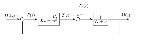
Where, the parameter values are as given:
Also, the performance specifications require the time constant of the system to be
The values of gains for the I controller are as follows:
Case 1. For
Case 2. For
Case 3. For a root separation factor of 10,
Concept Used:
- The transfer functions for the block diagram are as shown below:
- The steady-state error of a system using final value theorem is:
Calculation:
From the block diagram as shown, the transfer functions are as:
Therefore, the response
And from the block diagram shown in figure, we have
On keeping the values of the parameters such that
Case 1. When
Since,
Therefore, for unit-ramp command response
Thus, the steady-state error for this design is:
Therefore, for zero command response
Thus, the steady-state error for this design is:
Case 2. When
Since,
Therefore, for unit-ramp command response
Thus, the steady-state error for this design is:
Therefore, for zero command response
Thus, the steady-state error for this design is:
Case 3. For a root separation factor of 10,
Since,
Therefore, for unit-ramp command response
Thus, the steady-state error for this design is:
Therefore, for zero command response
Thus, the steady-state error for this design is:
Conclusion:
The steady-state error values for all the cases are:
Case 1. For
Error due to unit-ramp command:
Error due to unit-ramp disturbance:
Case 2. For
Error due to unit-ramp command:
Error due to unit-ramp disturbance:
Case 3. For a root separation factor of 10,
Error due to unit-ramp command:
Error due to unit-ramp disturbance:
Want to see more full solutions like this?
Chapter 10 Solutions
EBK SYSTEM DYNAMICS


- The figure illustrates the nonpermanent connection of a steel cylinder head to a grade 30 cast-iron pressure vessel using 73 bolts. A confined gasket seal has an effective sealing diameter D of 0.9 m. The cylinder pressure is cycled between a minimum pressure of zero and a maximum pressure p, of 535 kPa. For the specifications given in the table for the specific problem assigned, select a suitable bolt length from the preferred sizes. Use Table A-17 for calculation purposes. Parameter Head thickness, A Cylinder thickness, B Value 16 mm 25 mm Internal diameter of the cylinder, C 0.8 m Gasket sealing diameter, D Bolt circle diameter, E Outer diameter of the cylinder head, F 0.9 m 1.0 m 1.1 m Bolt grade ISO 10.9 Bolt diameter, d 10 mm F E D 111 Find a suitable bolt length. Then, determine the bolt stiffness, material stiffness and stiffness constant of the joint. The bolt length is The bolt stiffness is mm. MN/m. The material stiffness is | The stiffness constant is MN/m.arrow_forwardProblem 3 A rotating shaft of 20 mm diameter is simply supported. The shaft is loaded with a transverse load of 10 kN as shown in the figure. The shaft is made from AISI 1095 hot-rolled steel. The surface has been machined. The shaft operate at temperature T = 450 °C. Consider a reliability factor of 95%. Determine (a) Calculate the reaction forces R₁ and R2* (b) Draw the shear force and bending moment diagrams and determine the maximum bending moment and shear force. 200 mm 20 mm 10,000 N -50 mm- C A B R₁ Not to scale. (c) Determine the critical location of the shaft and the maximum effective stresses, (d) Calculate the static safety factor against yielding. (e) Determined the endurance limit, adjusted as necessary with Marin factors. (f) Calculate the fatigue factor of safety based on achieving infinite life (g) If the fatigue factor of safety is less than 1, then estimate the life of the part in number of rotations, based on the ultimate strength of the material at T = 450 °C.arrow_forwardAn air duct heater consists of an aligned array of electrical heating elements in which the longitudinal and transverse pitches are SL = ST = 24 mm. There are 3 rows of elements in the flow direction (NL = 3) and 4 elements per row (NT = 4). Atmospheric air with an upstream velocity of 12 m/s and a temperature of 25°C moves in cross flow over the elements, which have a diameter of 12 mm, a length of 250 mm, and are maintained at a surface temperature of 350°C. (a) Determine the total rate of heat transfer to the air and the temperature of the air leaving the duct heater. (b) Determine the pressure drop across the element bank and the fan power requirement. (c) Compare the average convection coefficient obtained in your analysis with the value for an isolated (single) element. Explain the difference between the results. (d) What effect would increasing the longitudinal and transverse pitches to 30 mm have on the exit temperature of the air, the total heat rate, and the…arrow_forward
- What is the elongation of the rod in inches? And what is the change in diameter? I dont want either answer rounded please! Thank you.arrow_forwardDraw the shear and bending-moment diagrams for the beam and loading shown, and determine the maximum absolute value of (a) the shear, (b) the bending moment. 300 lb 240 lb 360 lb C D E A 4 in. 3 in. 4 in. 5 in. Fig. P12.5arrow_forwardA commercial office building is located in the city of Lansing, Michigan, and is heatedusing a gaseous fuel with a heating value of 725 Btu/std ft3. The indoor designtemperature is 71ºF. The heat load for the building is known to be 250,000 Btu/hr. Thisheat load accounts for the fact that there are internal heat gains in the building, due tothe presence of people and electronic equipment (e.g., lights and radios). People in thebuilding are usually seated and involved in light activity.a) The furnace had an initial efficiency factor of 73% when installed, but since thenefficiency-improvement retrofits were implemented that raised the efficiency factorto its present value of 82%. The building was designed using the 99% designheating temperature value for the city to determine the outdoor design temperature.Evaluate the annual fuel quantity (in std ft3) required to heat the building, using thedegree-day or bin method.b) Seventy people use the building, but the occupancy pattern for the…arrow_forward
- The volumetric flow rate of air through a duct transition of the type shown in Table 12-9b (rectangular with two parallel sides) is 2 m3/s. The duct before the transition issquare, with a height of 50 cm. The expansion ratio across the transition is 4 (i.e., theduct area after the transition is 4 times greater than the duct area before the transition).a) Determine the pressure loss (in Pa) across the transition if the exit from the duct isabrupt (i.e., the diverging angle of the transition is 180º).b) Determine the percentage reduction in pressure loss for a transition diverging angleof 20º compared to the one in part (a).c) The head HVAC engineer requires the pressure loss across the transition to bereduced to less than 50% of the pressure loss for an abrupt exit (i.e., the case in part(a)), and suggests a transition diverging angle of 45º. Will this new diverging angleachieve the required reduction in pressure loss? Justify your answer.d) For a transition diverging angle of 90º, the…arrow_forwardThe volumetric flow rate of air through a duct transition of the type shown in Table 12-9b (rectangular with two parallel sides) is 2 m3/s. The duct before the transition issquare, with a height of 50 cm. The expansion ratio across the transition is 4 (i.e., theduct area after the transition is 4 times greater than the duct area before the transition).a) Determine the pressure loss (in Pa) across the transition if the exit from the duct isabrupt (i.e., the diverging angle of the transition is 180º).b) Determine the percentage reduction in pressure loss for a transition diverging angleof 20º compared to the one in part (a).c) The head HVAC engineer requires the pressure loss across the transition to bereduced to less than 50% of the pressure loss for an abrupt exit (i.e., the case in part(a)), and suggests a transition diverging angle of 45º. Will this new diverging angleachieve the required reduction in pressure loss? Justify your answer.d) For a transition diverging angle of 90º, the…arrow_forwardAuto Controls The figure is a schematic diagram of an aircraft elevator control system. The input to the systemin the deflection angle of the control lever , and the output is the elevator angle phi.show that for each angle theta of the control lever ,there is a corresponding elevator angle phi. Then find Y(s)/theta(s) and simplify the resulting transfer function . Also note from the diagram that y and phi is related Show full solution, no copied solutionsarrow_forward
 Elements Of ElectromagneticsMechanical EngineeringISBN:9780190698614Author:Sadiku, Matthew N. O.Publisher:Oxford University Press
 Mechanics of Materials (10th Edition)Mechanical EngineeringISBN:9780134319650Author:Russell C. HibbelerPublisher:PEARSON
 Thermodynamics: An Engineering ApproachMechanical EngineeringISBN:9781259822674Author:Yunus A. Cengel Dr., Michael A. BolesPublisher:McGraw-Hill Education
 Control Systems EngineeringMechanical EngineeringISBN:9781118170519Author:Norman S. NisePublisher:WILEY
 Mechanics of Materials (MindTap Course List)Mechanical EngineeringISBN:9781337093347Author:Barry J. Goodno, James M. GerePublisher:Cengage Learning
 Engineering Mechanics: StaticsMechanical EngineeringISBN:9781118807330Author:James L. Meriam, L. G. Kraige, J. N. BoltonPublisher:WILEY