
Concept explainers
Videos
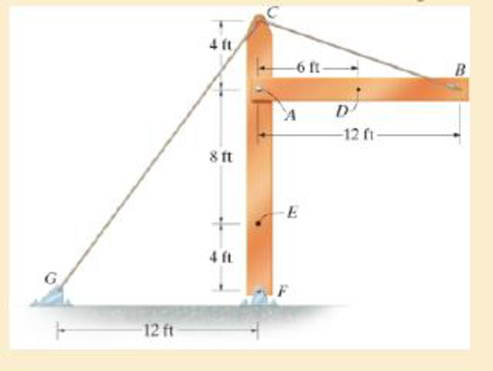
The beam AB is pin supported at A and supported by a cable BC. A separate cable CG is used to hold up the frame. If AB weighs 120 lb/ft and the column FC has a weight of 180 lb/ft, determine the resultant internal loadings acting on cross sections located at points D and E.
Answer to Problem 1RP
The resultant internal loadings at cross section at D are
The resultant internal loadings at cross section at E are
Explanation of Solution
Given information:
The beam AB is pin supported at A and supported by a cable BC.
The weight of the beam AB is
The weight of the column FC is
Calculation:
Find the loading at the center of the beam AB
Substitute
Convert the unit from lb to kip.
Sketch the Free Body Diagram of the beam AB shown in Figure 1.
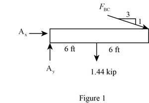
Refer to Figure 1.
Find the angle of cable BC to the horizontal
Find the tension in cable BC as shown below.
Take moment about A is Equal to zero.
Find the support reaction at A as shown below.
Apply the Equations of Equilibrium as shown below.
Summation of forces along horizontal direction is Equal to zero.
Summation of forces along vertical direction is Equal to zero.
Find the loading at the center of the beam AD
Substitute
Convert the unit from lb to kip.
Sketch the Free Body Diagram of the section for point D as shown in Figure 2.
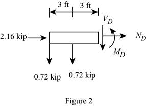
Refer to Figure 2.
Find the internal loadings as shown below.
Apply the Equations of Equilibrium as shown below.
Summation of forces along horizontal direction is Equal to zero.
Summation of forces along vertical direction is Equal to zero.
Take moment about D is Equal to zero.
Hence, the resultant internal loadings at cross section at D are
Find the loading at the center of the column FC
Substitute
Convert the unit from lb to kip.
Sketch the Free Body Diagram of the beam FC shown in Figure 3.
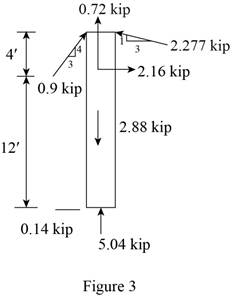
Refer to Figure 3.
Find the angle of cable CG to the horizontal.
Find the tension in cable CG as shown below.
Summation of forces along horizontal direction is Equal to zero.
Find the loading at the center of the column FE
Substitute
Convert the unit from lb to kip.
Sketch the Free Body Diagram of the section for point E as shown in Figure 4.
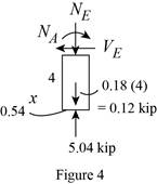
Refer to Figure 4.
Find the internal loadings as shown below.
Apply the Equations of Equilibrium as shown below.
Summation of forces along horizontal direction is Equal to zero.
Summation of forces along vertical direction is Equal to zero.
Take moment about E is Equal to zero.
Therefore, the resultant internal loadings at cross section at E are
Want to see more full solutions like this?
Chapter 1 Solutions
Mechanics of Materials
Additional Engineering Textbook Solutions
Starting Out with Java: From Control Structures through Objects (7th Edition) (What's New in Computer Science)
Degarmo's Materials And Processes In Manufacturing
Starting Out with C++: Early Objects (9th Edition)
Computer Science: An Overview (13th Edition) (What's New in Computer Science)
Introduction To Programming Using Visual Basic (11th Edition)
Starting Out with Python (4th Edition)


- Auto Controls Hand sketch the root Focus of the following transfer function How many asymptotes are there ?what are the angles of the asymptotes?Does the system remain stable for all values of K NO COPIED SOLUTIONSarrow_forward-400" 150" in Datum 80" 90" -280"arrow_forwardUsing hand drawing both of themarrow_forward
- A 10-kg box is pulled along P,Na rough surface by a force P, as shown in thefigure. The pulling force linearly increaseswith time, while the particle is motionless att = 0s untilit reaches a maximum force of100 Nattimet = 4s. If the ground has staticand kinetic friction coefficients of u, = 0.6 andHU, = 0.4 respectively, determine the velocityof the A 1 0 - kg box is pulled along P , N a rough surface by a force P , as shown in the figure. The pulling force linearly increases with time, while the particle is motionless at t = 0 s untilit reaches a maximum force of 1 0 0 Nattimet = 4 s . If the ground has static and kinetic friction coefficients of u , = 0 . 6 and HU , = 0 . 4 respectively, determine the velocity of the particle att = 4 s .arrow_forwardCalculate the speed of the driven member with the following conditions: Diameter of the motor pulley: 4 in Diameter of the driven pulley: 12 in Speed of the motor pulley: 1800 rpmarrow_forward4. In the figure, shaft A made of AISI 1010 hot-rolled steel, is welded to a fixed support and is subjected to loading by equal and opposite Forces F via shaft B. Stress concentration factors K₁ (1.7) and Kts (1.6) are induced by the 3mm fillet. Notch sensitivities are q₁=0.9 and qts=1. The length of shaft A from the fixed support to the connection at shaft B is 1m. The load F cycles from 0.5 to 2kN and a static load P is 100N. For shaft A, find the factor of safety (for infinite life) using the modified Goodman fatigue failure criterion. 3 mm fillet Shaft A 20 mm 25 mm Shaft B 25 mmarrow_forward
 Elements Of ElectromagneticsMechanical EngineeringISBN:9780190698614Author:Sadiku, Matthew N. O.Publisher:Oxford University Press
 Mechanics of Materials (10th Edition)Mechanical EngineeringISBN:9780134319650Author:Russell C. HibbelerPublisher:PEARSON
 Thermodynamics: An Engineering ApproachMechanical EngineeringISBN:9781259822674Author:Yunus A. Cengel Dr., Michael A. BolesPublisher:McGraw-Hill Education
 Control Systems EngineeringMechanical EngineeringISBN:9781118170519Author:Norman S. NisePublisher:WILEY
 Mechanics of Materials (MindTap Course List)Mechanical EngineeringISBN:9781337093347Author:Barry J. Goodno, James M. GerePublisher:Cengage Learning
 Engineering Mechanics: StaticsMechanical EngineeringISBN:9781118807330Author:James L. Meriam, L. G. Kraige, J. N. BoltonPublisher:WILEY