
Concept explainers
Videos
Figure Pl.5 shows the topology of a photo-voltaic (PV) system that uses solar cells to supply electrical power to a residence with hybrid electnc vehicle toads (Gurkavnak. 2009). The system consists of a PV array to collect the sun's rays, a battery pack to store energy during the day. a dc/ac inverter to supply ac power to the load, and a bidirectional dc/dc converter to control the terminal voltage of the solar array according to a maxunum power point tracking (MPPT) algorithm. In case of sufficient solar power (solar insolation), the dc/dc converter charges die battery and die solar array supplies power to the load through the dc/ac inverter. Widi less or no solar energy (solar non-insolation). power is supplied from the battery to the load through the dc/dc converter and die dc/ac inverter. Thus, the dc/dc converter must be bidirectional to be able to charge and discharge the batlery. With the MPPT controller providing the reference voltage, the converter operates as a step-up converter (boost) to discharge the battery if the battery is full or a step-down (buck) converter, which charges die batlery if it is not full.7
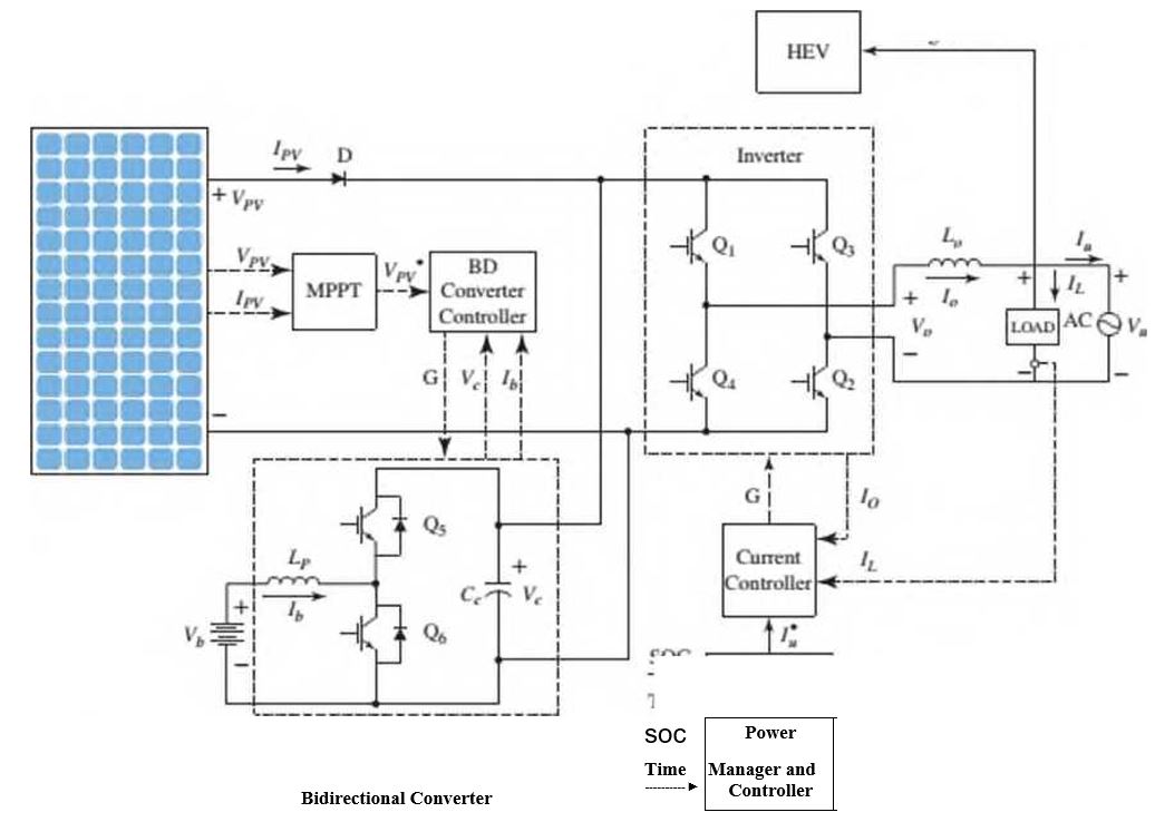
In Figure Pl.5, the Inverter is controlled by die Power Manager and Controller through the Current Controller. The Power Manager and Controller directs the Inverter to take power either from the battery, via the Bidirectional Converter, or the solar array.
of charge (SOC). Draw the follow ing two functional block diagrams for this system:
- A diagram that illustrates the conversion of solar irradiation into energy stored in the battery. In that diagram, the input is the solar irradiance. r(t), and the output is the battery voltage. Vb(t).
- The main diagram, in w hich the input is the desired output voltage. Vr(t) and the output is the actual inverter output voltage, Vo(t) Both of these functional block diagrams should show their major components, including the PV array, MPPT controller, dc/dc converter, battery pack, dc/ac inverter, current controller, and the Power Manager and Controller. Show all signals, including intermediate voltages and currents, time of day. and the SOC of the battery.
Want to see the full answer?
Check out a sample textbook solution
Chapter 1 Solutions
CONTROL SYSTEMS ENGINEERING


- [Q2]: The cost information supplied by the cost accountant is as follows:Sales 20,00 units, $ 10 per unitCalculate the (a/ newsale guantity and (b) new selling price to earn the sameVariable cost $ 6 per unit, Fixed Cost $ 30,000, Profit $ 50,000profit ifi) Variable cost increases by $ 2 per unitil) Fixed cost increase by $ 10,000Ili) Variable cost increase by $ 1 per unit and fixed cost reduces by $ 10,000arrow_forwardcan you please help me perform Visual Inspection and Fractography of the attatched image: Preliminary examination to identify the fracture origin, suspected fatigue striation, and corrosion evidences.arrow_forwardcan you please help[ me conduct Causal Analysis (FTA) on the scenario attatched: FTA diagram which is a fault tree analysis diagram will be used to gain an overview of the entire path of failure from root cause to the top event (i.e., the swing’s detachment) and to identify interactions between misuse, material decay and inspection errors.arrow_forward
- hi can you please help me in finding the stress intensity factor using a k-calcluator for the scenario attathced in the images.arrow_forwardHi, can you please help me .Identify and justify suitable analytical techniques of the scenario below, bearing in mind the kinds of information being handled to reach a conclusion (methodology). A child swing set was discovered to have failed at the fixing at the top of the chains connecting the seat to the top of the swing set. A 12 mm threaded steel bolt, connecting the shackle to the top beam, failed at the start of the threaded region on the linkage closest to the outside side of the swing set . The linkage and bolts were made of electro galvanised mild steel . The rigid bar chain alternatives and fixings were of the same material and appeared to be fitted in accordance with guidelines. The yield strength of the steel used is 260 MPa and the UTS is 380 MPa. The bolt that failed was threaded using a standard thread with a pitch (distance between threads) of 1.75 mm and a depth of approximately 1.1 mm. The swing set in question had been assigned to ‘toddlers’ with the application of…arrow_forwardHi, can you please define and calculate the failure mode of the linkage that failed on the swing (images added) : A child swing set was discovered to have failed at the fixing at the top of the chains connecting the seat to the top of the swing set. A 12 mm threaded steel bolt, connecting the shackle to the top beam, failed at the start of the threaded region on the linkage closest to the outside side of the swing set . The linkage and bolts were made of electro galvanised mild steel . The rigid bar chain alternatives and fixings were of the same material and appeared to be fitted in accordance with guidelines. The yield strength of the steel used is 260 MPa and the UTS is 380 MPa. The bolt that failed was threaded using a standard thread with a pitch (distance between threads) of 1.75 mm and a depth of approximately 1.1 mm. The swing set in question had been assigned to ‘toddlers’ with the application of a caged-type seat. However, the location was within the play area not…arrow_forward
- Page 11-68. The rectangular plate shown is subjected to a uniaxial stress of 2000 psi. Compute the shear stress and the tensile developed on a plane forming an angle of 30° with the longitud axis of the member. (Hint: Assume a cross-sectional area of unity) 2000 psi 2000 psi hparrow_forward11-70. A shear stress (pure shear) of 5000 psi exists on an element. (a) Determine the maximum tensile and compressive stresses caused in the element due to this shear. (b) Sketch the element showing the planes on which the maximum tensile and compressive stresses act.arrow_forward11-20. An aluminum specimen of circular cross section, 0.50 in. in diameter, ruptured under a tensile load of 12,000 lb. The plane of failure was found to be at 48° with a plane perpendicular to the longitudinal axis of the specimen. (a) Compute the shear stress on the failure plane. (b) Compute the maximum tensile stress. (c) Compute the tensile stress on the failure plane. hparrow_forward
- A long flat steel bar 13 mm thick and 120 mm wide has semicircular grooves as shown and carries a tensile load of 50 kN Determine the maximum stress if plate r= 8mm r=21mm r=38mmarrow_forwardProblem 13: F₁ = A =250 N 30% Determine the moment of each of the three forces about point B. F₂ = 300 N 60° 2 m -3 m B 4 m F3=500 Narrow_forward3 kN 3 kN 1.8 kN/m 80 mm B 300 mm D an 1.5 m-1.5 m--1.5 m- PROBLEM 5.47 Using the method of Sec. 5.2, solve Prob. 5.16 PROBLEM 5.16 For the beam and loading shown, determine the maximum normal stress due to bending on a transverse section at C.arrow_forward
 Principles of Heat Transfer (Activate Learning wi...Mechanical EngineeringISBN:9781305387102Author:Kreith, Frank; Manglik, Raj M.Publisher:Cengage Learning