
Concept explainers
Videos
Figure Pl.5 shows the topology of a photo-voltaic (PV) system that uses solar cells to supply electrical power to a residence with hybrid electnc vehicle toads (Gurkavnak. 2009). The system consists of a PV array to collect the sun's rays, a battery pack to store energy during the day. a dc/ac inverter to supply ac power to the load, and a bidirectional dc/dc converter to control the terminal voltage of the solar array according to a maxunum power point tracking (MPPT) algorithm. In case of sufficient solar power (solar insolation), the dc/dc converter charges die battery and die solar array supplies power to the load through the dc/ac inverter. Widi less or no solar energy (solar non-insolation). power is supplied from the battery to the load through the dc/dc converter and die dc/ac inverter. Thus, the dc/dc converter must be bidirectional to be able to charge and discharge the batlery. With the MPPT controller providing the reference voltage, the converter operates as a step-up converter (boost) to discharge the battery if the battery is full or a step-down (buck) converter, which charges die batlery if it is not full.7
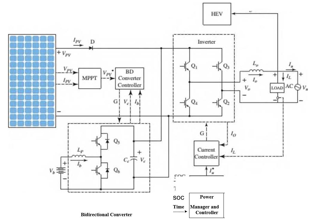
In Figure Pl.5, the Inverter is controlled by die Power Manager and Controller through the Current Controller. The Power Manager and Controller directs the Inverter to take power either from the battery, via the Bidirectional Converter, or the solar array.
of charge (SOC). Draw the follow ing two functional block diagrams for this system:
- A diagram that illustrates the conversion of solar irradiation into energy stored in the battery. In that diagram, the input is the solar irradiance. r(t), and the output is the battery voltage. Vb(t).
- The main diagram, in w hich the input is the desired output voltage. Vr(t) and the output is the actual inverter output voltage, Vo(t) Both of these functional block diagrams should show their major components, including the PV array, MPPT controller, dc/dc converter, battery pack, dc/ac inverter, current controller, and the Power Manager and Controller. Show all signals, including intermediate voltages and currents, time of day. and the SOC of the battery.
Want to see the full answer?
Check out a sample textbook solution
Chapter 1 Solutions
CONTROL SYSTEMS ENGINEERING - WILEYPLUS


- CORRECT ANSWER WITH COMPLETE FBD ONLY. I WILL UPVOTE. A torque wrench is used to tighten the pipe shown.Dimensions: S1 = 400 mm; S2 = 250 mm; S3 = 100 mmModulus of Rigidity G = 78 GPa1. The diameter of the solid pipe is 20 mm. How much is themaximum force P (N) that can be applied based on theallowable shear stress of 60 MPa?2. For a hollow pipe with 50 mm outside diameter and is 6 mmthick, compute for the maximum force P (kN) that can beapplied such that the angle of twist at A does not exceed 5degrees.3. The torque applied to tighten the hollow pipe is 200 N-m.Given: Pipe outside diameter = 50 mm Pipe thickness = 6 mmSolve for the resulting maximum shear stress (MPa) in the pipe.arrow_forwardCorrect answer and complete fbd only. I will upvote. 6: The shaft carries a total torque T0 that is uniformly distributedover its length L. Determine the angle of twist (degrees) of the shaft in termsif T0 = 1.2 kN-m, L = 2 m, G = 80 GPa, and diameter = 120 mm.arrow_forward2. Calculate the force in all members of the trusses shown using the method of joints. A 5525 lb C 3500 lb BY 14'-0" D 10'- 0" 6250 lb 10'- 0" Earrow_forward
- Correct answer and complete fbd only. I will upvote. 8: The steel rod fits loosely inside the aluminum sleeve. Both components are attached to a rigid wall at A andjoined together by a pin at B. Because of a slight misalignmentof the pre-drilled holes, the torque T0 = 750 N-m was appliedto the steel rod before the pin could be inserted into theholes. Determine the torque (N-m) in each component afterT0 was removed. Use G = 80 GPa for steel and G = 28 GPa foraluminumarrow_forwardCorrect answer and complete fbd only. I will upvote. 9: The two steel shafts, each with one end builtinto a rigid support, have flanges attached to their freeends. The flanges are to be bolted together. However,initially there is a 6⁰ mismatch in the location of the boltholes as shown in the figure. Determine the maximumshear stress(ksi) in each shaft after the flanges have beenbolted together. The shear modulus of elasticity for steelis 12 x 106 psi. Neglect deformations of the bolts and theflanges.arrow_forwardCorrect answer and complete fbd only. I will upvote. The tapered, wrought iron shaft carriesthe torque T = 2000 lb-in at its free end. Determine theangle of twist (degrees) of the shaft. Use G = 10 x 106psi for wrought ironarrow_forward
- Correct answer and complete fbd only. I will upvote. The compound shaft, consisting of steel and aluminumsegments, carries the two torques shown in the figure. Determine themaximum permissible value of T subject to the following designconditions: τst ≤ 83 MPa, τal ≤ 55 MPa, and θ ≤ 6⁰ (θ is the angle ofrotation of the free end). Use G =83 GPa for steel and G = 28 GPa foraluminum.arrow_forwardThe solid compound shaft, made of threedifferent materials, carries the two torques shown. Theshear moduli are 28 GPa for aluminum, 83 GPa for steel,and 35 GPa for bronze.1. Calculate the maximum shear stress (MPa) in eachmaterial.2. Find the angle of rotation (degrees) of the free endof the shaft.arrow_forwardCorrect answer only please. I will upvote. The velocity of a particle moves along the x-axis and is given by the equation ds/dt = 40 - 3t^2 m/s. Calculate the acceleration at time t=2 s and t=4 s. Calculate also the total displacement at the given interval. Assume at t=0 s=5m.Write the solution using pen and draw the graph if needed.arrow_forward
- I want the steps of operation of the circuit, clearly in detail. Please. LV1arrow_forwardComplet the solution: Vavg Ti Te Ts Qhexp Nuexp htheo Re Nutheo Error (m/s) (°C) (°C) (°C) (W) 2.11 18.8 21.3 45.8 2.61 18.5 20.8 46.3 Heat transfer Given data: a= 10 cm. L= 10 cm. b= 20 cm. H=40cm. ⚫ a = 10, cm: This could represent the width of the duct. ⚫b=20, cm: This might be the height of the duct. ⚫L = 10, cm: This usually stands for the length of the duct in the direction of flow. ⚫H=40, cm: This could indicate the height of some component or another duct-related dimension, but the exact meaning depends on the experiment's context.arrow_forwardplease explain each step and include drawings on the phase diagram. thanksarrow_forward
 Principles of Heat Transfer (Activate Learning wi...Mechanical EngineeringISBN:9781305387102Author:Kreith, Frank; Manglik, Raj M.Publisher:Cengage Learning