Concept explainers
Videos
By selecting three different types of measurement systems and identify which attributes of the system comprise the measurement stages.
Answer to Problem 1.1P
Following of measurement systems has been selected and attributed.
- Microphone/Amplifier/Speaker System.
- Room Heating Thermostat.
- Handheld Micrometer.
Explanation of Solution
Given information:
Measurement systems that we have studied.
The three distinct types of measurement systems are the speaker system, room heating thermostat, and handheld micrometer.
(i) Microphone/Amplifier/Speaker System:
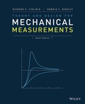
Speaker systems are the principal components of the audio system. The principal components of a speaker system are the transducer, amplifier, and an output stage which consist about an output transducer. At the transducer stage, the input transducer collects sound waves and turns it to electrical energy.
At signal conditioning staging, the speaker system amplifies the electrical energy and at the output staging, the electrical energy is repeatedly converted into sound signals which are of high amplitude. That is when the intent of the speaker system is served. There are just transducer stage, signal conditioning stage and output staging.
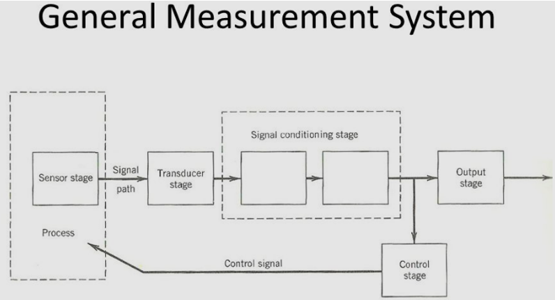
(ii) Room Heating Thermostat:
Thermostats are primarily used to measure the temperatures. A thermostat senses the temperature of the room and thereby switches the cooling apparatus which is implemented in the place.
Select room thermostats equipped in houses estimate the temperature of the air in the room, if it is cool it will turn on the central heating, and when it gets too hot it tells the central heating to set off. Room thermostats need an unrestricted flow of air to sense the heat, so they must not be blocked by screens or fittings or put near heat sources.
In the room heating thermostat at sensor stage, it sense the temperature of the room and imparts a sign to the transducer, the transducer is combined to the signal conditioning stage and sends an output signal that might be the actuating the buzzer or switching on the room heating device consequently.
A feedback signal is received before the output stage and transferred back to the sensor stage continuously to control the heat of the room if it is getting too hot it will turn off the heating equipment automatically.
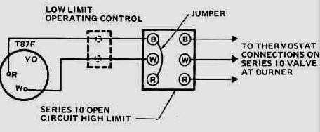
(iii) Handheld Micrometer:
The handheld micrometers are recognized for their precision but having a short measuring range these are superseded with laser micrometers.
Short lengths and depths of the channels can be found by using the handheld micrometer. These measurements are subjected to alternate, when the operator and operating conditions differs.
The micrometer should be taken with the hand and the object is to be embedded in the grips of the micrometer.
A torque must be employed against the machine taken in the jaws of the micrometer. The micrometer scale is displaced to some extent calibrated on the scale.
Conclusion:
Following measurement systems have been selected and attributed.
- Microphone/Amplifier/Speaker System.
- Room Heating Thermostat.
- Handheld Micrometer.
Want to see more full solutions like this?
Chapter 1 Solutions
Theory and Design for Mechanical Measurements


- This is an exam review question. The answer is Pmin = 622.9 lb but whyarrow_forwardPlease do not use any AI tools to solve this question. I need a fully manual, step-by-step solution with clear explanations, as if it were done by a human tutor. No AI-generated responses, please.arrow_forwardPlease do not use any AI tools to solve this question. I need a fully manual, step-by-step solution with clear explanations, as if it were done by a human tutor. No AI-generated responses, please.arrow_forward
- Please do not use any AI tools to solve this question. I need a fully manual, step-by-step solution with clear explanations, as if it were done by a human tutor. No AI-generated responses, please.arrow_forwardThis is an old practice exam. Fce = 110lb and FBCD = 62 lb but whyarrow_forwardQuiz/An eccentrically loaded bracket is welded to the support as shown in Figure below. The load is static. The weld size for weld w1 is h1 = 4mm, for w2 h2 = 6mm, and for w3 is h3 =6.5 mm. Determine the safety factor (S.f) for the welds. F=29 kN. Use an AWS Electrode type (E100xx). 163 mm S 133 mm 140 mm Please solve the question above I solved the question but I'm sure the answer is wrong the link : https://drive.google.com/file/d/1w5UD2EPDiaKSx3W33aj Rv0olChuXtrQx/view?usp=sharingarrow_forward
- Q2: (15 Marks) A water-LiBr vapor absorption system incorporates a heat exchanger as shown in the figure. The temperatures of the evaporator, the absorber, the condenser, and the generator are 10°C, 25°C, 40°C, and 100°C respectively. The strong liquid leaving the pump is heated to 50°C in the heat exchanger. The refrigerant flow rate through the condenser is 0.12 kg/s. Calculate (i) the heat rejected in the absorber, and (ii) the COP of the cycle. Yo 8 XE-V lo 9 Pc 7 condenser 5 Qgen PG 100 Qabs Pe evaporator PRV 6 PA 10 3 generator heat exchanger 2 pump 185 absorberarrow_forwardQ5:(? Design the duct system of the figure below by using the balanced pressure method. The velocity in the duct attached to the AHU must not exceed 5m/s. The pressure loss for each diffuser is equal to 10Pa. 100CFM 100CFM 100CFM ☑ ☑ 40m AHU -16m- 8m- -12m- 57m 250CFM 40m -14m- 26m 36m ☑ 250CFMarrow_forwardA mass of ideal gas in a closed piston-cylinder system expands from 427 °C and 16 bar following the process law, pv1.36 = Constant (p times v to the power of 1.36 equals to a constant). For the gas, initial : final pressure ratio is 4:1 and the initial gas volume is 0.14 m³. The specific heat of the gas at constant pressure, Cp = 0.987 kJ/kg-K and the specific gas constant, R = 0.267 kJ/kg.K. Determine the change in total internal energy in the gas during the expansion. Enter your numerical answer in the answer box below in KILO JOULES (not in Joules) but do not enter the units. (There is no expected number of decimal points or significant figures).arrow_forward
- my ID# 016948724. Please solve this problem step by steparrow_forwardMy ID# 016948724 please find the forces for Fx=0: fy=0: fz=0: please help me to solve this problem step by steparrow_forwardMy ID# 016948724 please solve the proble step by step find the forces fx=o: fy=0; fz=0; and find shear moment and the bending moment diagran please draw the diagram for the shear and bending momentarrow_forward
 Elements Of ElectromagneticsMechanical EngineeringISBN:9780190698614Author:Sadiku, Matthew N. O.Publisher:Oxford University Press
 Mechanics of Materials (10th Edition)Mechanical EngineeringISBN:9780134319650Author:Russell C. HibbelerPublisher:PEARSON
 Thermodynamics: An Engineering ApproachMechanical EngineeringISBN:9781259822674Author:Yunus A. Cengel Dr., Michael A. BolesPublisher:McGraw-Hill Education
 Control Systems EngineeringMechanical EngineeringISBN:9781118170519Author:Norman S. NisePublisher:WILEY
 Mechanics of Materials (MindTap Course List)Mechanical EngineeringISBN:9781337093347Author:Barry J. Goodno, James M. GerePublisher:Cengage Learning
 Engineering Mechanics: StaticsMechanical EngineeringISBN:9781118807330Author:James L. Meriam, L. G. Kraige, J. N. BoltonPublisher:WILEY