What are UML diagrams? Can describe several typical diagrams.
What are UML diagrams? Can describe several typical diagrams.
UML Standards for Unified Modeling Language which is used in software engineering it is a rich language that can be used to model an application structures, behavior. There are 14 UML diagram types.
A UML diagram is a partial graphical representation (view) of a model of a system under design, implementation, or already in existence. UML diagram contains graphical elements . UML nodes connected with edges (also known as paths or flows) - that represent elements in the UML model of the designed system. The UML model of the system might also contain other documentation such as use cases written as templated text.
The kind of the diagram is defined by the primary graphical symbols shown on the diagram.
List of UML Diagram Types
Types of UML diagrams with structure diagrams coming first and behavioral diagrams starting from position 8
- Class Diagram
- Component Diagram
- Deployment Diagram
- Object Diagram
- Package Diagram
- Profile Diagram
- Composite Structure Diagram
- Use Case Diagram
- Activity Diagram
- State Machine Diagram
- Sequence Diagram
- Communication Diagram
- Interaction Overview Diagram
- Timing Diagram
class diagram
A class diagram in the Unified Modeling Language (UML) is a type of static structure diagram that describes the structure of a system by showing the system's classes, their attributes, operations (or methods), and the relationships among objects.
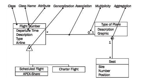
Elements of the class diagram
Class: A class represents a relevant concept from the domain, a set of persons, objects, or ideas that are depicted in the IT system
Attribute:An attribute of a class represents a characteristic of a class that is of interest for the user of the IT system:
Aggregation : An aggregation is a special case of an association (see above) meaning "consists of"
Use case diagrams
Use case diagrams are considered for high level requirement analysis of a system. When the requirements of a system are analyzed, the functionalities are captured in use cases.
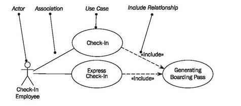
Elements of the use case diagram
Actor: Actors can be a human user, some internal applications, or may be some external application.
Guidelines to draw an efficient use case diagram
-
The name of a use case is very important. The name should be chosen in such a way so that it can identify the functionalities performed.
-
Give a suitable name for actors.
-
Show relationships and dependencies clearly in the diagram.
-
Do not try to include all types of relationships, as the main purpose of the diagram is to identify the requirements.
-
Use notes whenever required to clarify some important points.
Sequence Diagram:
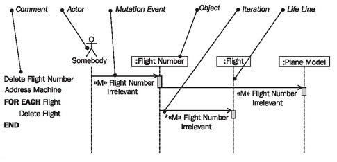
The elements of sequence diagrams
Lifeline
The lifeline of an object represents a life (over the course of time). The rectangle, meaning the "thick part" of the lifeline shows when the object is active.
Sequence diagrams in UML show how objects interact with each other and the order those interactions occur. It’s important to note that they show the interactions for a particular scenario. The processes are represented vertically and interactions are show as arrows.
Component Diagram:
A component diagram displays the structural relationship of components of a software system. These are mostly used when working with complex systems that have many components. Components communicate with each other using interfaces. The interfaces are linked using connectors. The images below shows a component diagram.
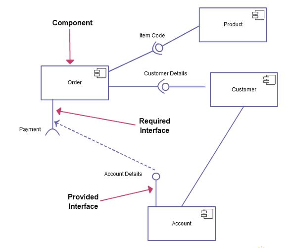
The purpose of the component diagram is
-
Visualize the components of a system.
-
Construct executables by using forward and reverse engineering.
-
Describe the organization and relationships of the components.
Statechart Diagram
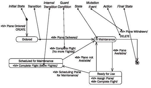
The main purposes of using Statechart diagrams
-
To model the dynamic aspect of a system.
-
To model the life time of a reactive system.
-
To describe different states of an object during its life time.
-
Define a state machine to model the states of an object.
Step by step
Solved in 2 steps with 5 images


