Vsupply R₁ R₂

Introductory Circuit Analysis (13th Edition)
13th Edition
ISBN:9780133923605
Author:Robert L. Boylestad
Publisher:Robert L. Boylestad
Chapter1: Introduction
Section: Chapter Questions
Problem 1P: Visit your local library (at school or home) and describe the extent to which it provides literature...

Related questions

Question

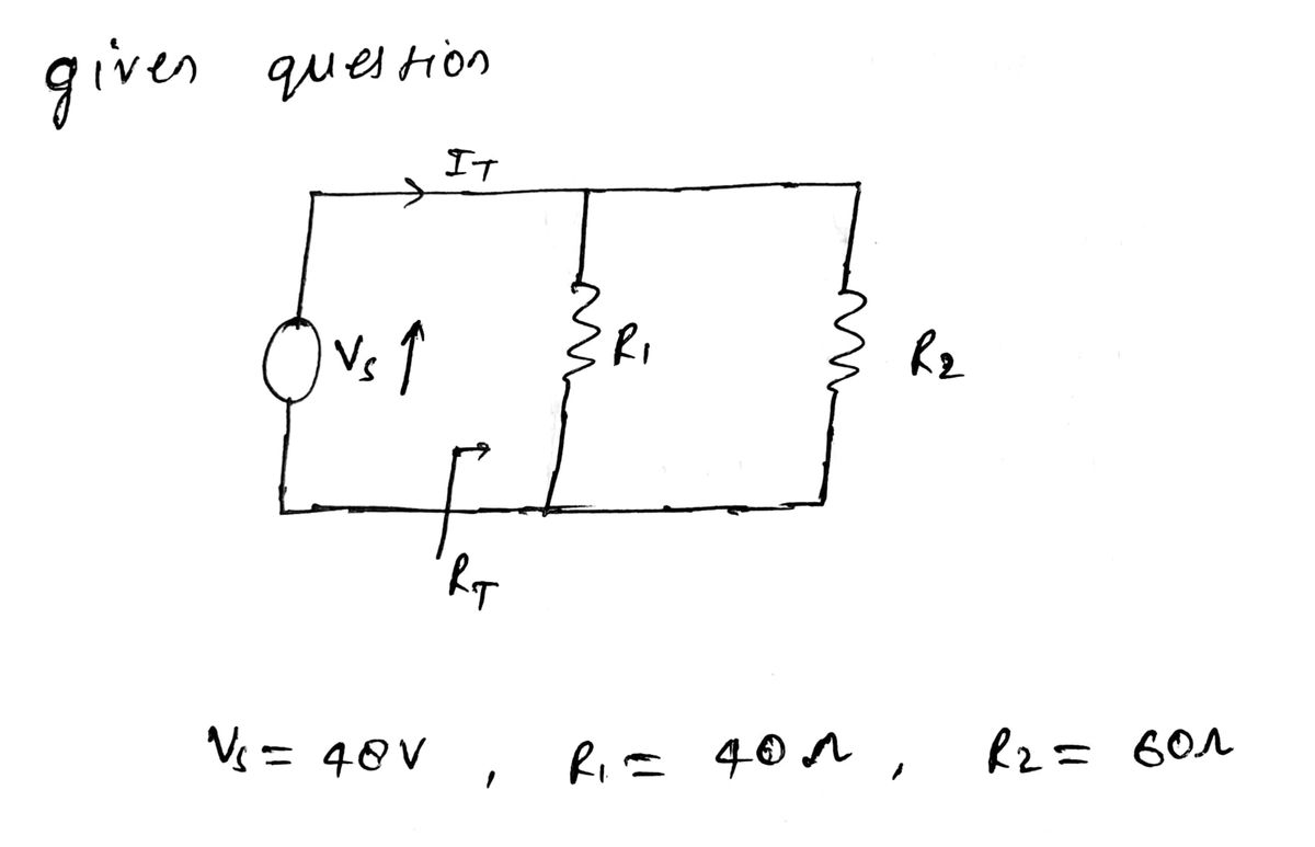
Transcribed Image Text:The diagram shows a simple electrical circuit with two main components:
1. **Voltage Source (Vsupply):**
- Represented by a circle with an arrow inside, indicating the direction of the supplied voltage.
2. **Resistors (R1 and R2):**
- Two resistors are placed in parallel, labeled as R1 and R2.
**Explanation of the Circuit:**
- This is a parallel circuit, where the voltage source (Vsupply) provides power to two resistors (R1 and R2) simultaneously.
- In a parallel circuit, the voltage across each component is the same, and the total current is the sum of currents through each path.
- The resistors are positioned such that they share the same voltage but may carry different currents depending on their resistance values.

Transcribed Image Text:### Circuit Analysis Problem
**Problem Statement:**
If the values for the circuit in Figure (1) are changed as follows:
- \( V_{\text{Supply}} = 48 \) Volts
- \( R_1 = 40 \, \Omega \)
- \( R_2 = 60 \, \Omega \)
Calculate \( R_{\text{Total}} \), \( I_{\text{Total}} \), \( I_1 \), and \( I_2 \) for the new values of the circuit.
Expert Solution
Step 1

Step by step
Solved in 3 steps with 3 images

Knowledge Booster


Learn more about
Need a deep-dive on the concept behind this application? Look no further. Learn more about this topic, electrical-engineering and related others by exploring similar questions and additional content below.Recommended textbooks for you
Introductory Circuit Analysis (13th Edition)
Electrical Engineering
ISBN:
9780133923605
Author:
Robert L. Boylestad
Publisher:
PEARSON

Delmar's Standard Textbook Of Electricity
Electrical Engineering
ISBN:
9781337900348
Author:
Stephen L. Herman
Publisher:
Cengage Learning

Programmable Logic Controllers
Electrical Engineering
ISBN:
9780073373843
Author:
Frank D. Petruzella
Publisher:
McGraw-Hill Education
Introductory Circuit Analysis (13th Edition)
Electrical Engineering
ISBN:
9780133923605
Author:
Robert L. Boylestad
Publisher:
PEARSON
Delmar's Standard Textbook Of Electricity
Electrical Engineering
ISBN:
9781337900348
Author:
Stephen L. Herman
Publisher:
Cengage Learning
Programmable Logic Controllers
Electrical Engineering
ISBN:
9780073373843
Author:
Frank D. Petruzella
Publisher:
McGraw-Hill Education

Fundamentals of Electric Circuits
Electrical Engineering
ISBN:
9780078028229
Author:
Charles K Alexander, Matthew Sadiku
Publisher:
McGraw-Hill Education

Electric Circuits. (11th Edition)
Electrical Engineering
ISBN:
9780134746968
Author:
James W. Nilsson, Susan Riedel
Publisher:
PEARSON

Engineering Electromagnetics
Electrical Engineering
ISBN:
9780078028151
Author:
Hayt, William H. (william Hart), Jr, BUCK, John A.
Publisher:
Mcgraw-hill Education,