Vs(t) In the following circuit find Vo(t) R1 ww 10 kQ L 80 mH R3 300 Ω WHI Vs(t) = 125 cos (500 t + 15°) mV R2 10 kg M CI с 25 nF WI Vo(t) R4 20 ΚΩ
Vs(t) In the following circuit find Vo(t) R1 ww 10 kQ L 80 mH R3 300 Ω WHI Vs(t) = 125 cos (500 t + 15°) mV R2 10 kg M CI с 25 nF WI Vo(t) R4 20 ΚΩ

Introductory Circuit Analysis (13th Edition)
13th Edition
ISBN:9780133923605
Author:Robert L. Boylestad
Publisher:Robert L. Boylestad
Chapter1: Introduction
Section: Chapter Questions
Problem 1P: Visit your local library (at school or home) and describe the extent to which it provides literature...

Related questions
Question
5.) please show step by step

Transcribed Image Text:### Circuit Analysis: Finding \( V_o(t) \)
#### Problem Statement
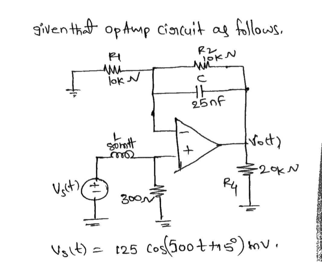
In the following circuit, find \( V_o(t) \).
#### Circuit Components
- **Resistors:**
- \( R_1 = 10 \, \text{k}\Omega \)
- \( R_2 = 10 \, \text{k}\Omega \)
- \( R_3 = 300 \, \Omega \)
- \( R_4 = 20 \, \text{k}\Omega \)
- **Inductor:**
- \( L = 80 \, \text{mH} \)
- **Capacitor:**
- \( C = 25 \, \text{nF} \)
- **Input Voltage Source:**
- \( V_s(t) = 125 \cos(500t + 15^\circ) \, \text{mV} \)
#### Circuit Configuration
- The circuit includes an operational amplifier (op-amp) in a configuration involving feedback through \( R_2 \) and the capacitor \( C \).
- The input voltage \( V_s(t) \) is applied across the inductor \( L \) and resistor \( R_3 \).
- The op-amp has two inputs: the inverting input connected to the junction of \( R_1 \), \( R_2 \), and \( C \), and the non-inverting input is grounded.
- The output voltage \( V_o(t) \) is taken from the output of the op-amp and connected through \( R_4 \) to ground.
#### Objective
Analyze the circuit to determine the expression for the output voltage \( V_o(t) \). Use the provided component values and source voltage to perform the analysis. This may involve applying circuit theorems, phasor analysis, and op-amp properties to derive \( V_o(t) \).
Expert Solution
Step 1

Step by step
Solved in 3 steps with 3 images

Knowledge Booster


Learn more about
Need a deep-dive on the concept behind this application? Look no further. Learn more about this topic, electrical-engineering and related others by exploring similar questions and additional content below.Recommended textbooks for you
Introductory Circuit Analysis (13th Edition)
Electrical Engineering
ISBN:
9780133923605
Author:
Robert L. Boylestad
Publisher:
PEARSON

Delmar's Standard Textbook Of Electricity
Electrical Engineering
ISBN:
9781337900348
Author:
Stephen L. Herman
Publisher:
Cengage Learning

Programmable Logic Controllers
Electrical Engineering
ISBN:
9780073373843
Author:
Frank D. Petruzella
Publisher:
McGraw-Hill Education
Introductory Circuit Analysis (13th Edition)
Electrical Engineering
ISBN:
9780133923605
Author:
Robert L. Boylestad
Publisher:
PEARSON
Delmar's Standard Textbook Of Electricity
Electrical Engineering
ISBN:
9781337900348
Author:
Stephen L. Herman
Publisher:
Cengage Learning
Programmable Logic Controllers
Electrical Engineering
ISBN:
9780073373843
Author:
Frank D. Petruzella
Publisher:
McGraw-Hill Education

Fundamentals of Electric Circuits
Electrical Engineering
ISBN:
9780078028229
Author:
Charles K Alexander, Matthew Sadiku
Publisher:
McGraw-Hill Education

Electric Circuits. (11th Edition)
Electrical Engineering
ISBN:
9780134746968
Author:
James W. Nilsson, Susan Riedel
Publisher:
PEARSON

Engineering Electromagnetics
Electrical Engineering
ISBN:
9780078028151
Author:
Hayt, William H. (william Hart), Jr, BUCK, John A.
Publisher:
Mcgraw-hill Education,