VS 1 Vpk 100 Hz ODeg 2.2uF IC=OV R1 m 1000 C2 1uF IC=OV >R2 2200


Quantization and Resolution
Quantization is a methodology of carrying out signal modulation by the process of mapping input values from an infinitely long set of continuous values to a smaller set of finite values. Quantization forms the basic algorithm for lossy compression algorithms and represents a given analog signal into digital signals. In other words, these algorithms form the base of an analog-to-digital converter. Devices that process the algorithm of quantization are known as a quantizer. These devices aid in rounding off (approximation) the errors of an input function called the quantized value.
Probability of Error
This topic is widely taught in many undergraduate and postgraduate degree courses of:

![The table provided is structured to display calculations for circuit values at two different frequencies: 1 kHz and 10 kHz. It is organized into columns for rectangular and polar forms under each frequency. Below is a transcription of the table content:
### Table Header:
- **Frequency (f) = 1 kHz**
- **Rectangular**
- **Polar**
- **Frequency (f) = 10 kHz**
- **Rectangular**
- **Polar**
### Circuit Value Equations:
1. \( X_{C1} = 1 / [2\pi(f)(C_1)] \)
2. \( X_{C2} = 1 / [2\pi(f)(C_2)] \)
3. \( R_T = R_1 + R_2 \)
4. \( X_{CT} = X_{C1} + X_{C2} \)
5. \( Z_T = R_T + jX_{CT} \)
6. \( I_T = V_S / Z_T \)
7. \( V_{C1} = I_T \times X_{C1} \)
8. \( V_{C2} = I_T \times X_{C2} \)
9. \( V_{R1} = I_T \times R_1 \)
10. \( V_{R2} = I_T \times R_2 \)
### Graph/Diagram Description:
There is no graph or diagram present in this table; it consists solely of placeholders for calculations based on the given formulas. The table is likely used in educational settings for illustrating calculations of reactance, impedance, current, and voltage values in electric circuits at different frequencies.
This layout supports students in learning how to compute these values in both rectangular and polar forms, enhancing their understanding of electrical circuit analysis.](/v2/_next/image?url=https%3A%2F%2Fcontent.bartleby.com%2Fqna-images%2Fquestion%2F946d2131-1df4-4d93-acc7-a27f80ccabfd%2Fe93440d6-1c30-4601-930c-223a5c618328%2Fr127byi2_processed.jpeg&w=3840&q=75)
Given circuit:
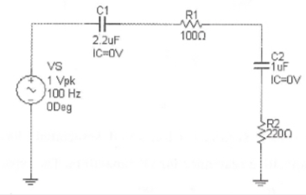
Asked to find the,
- Capacitive reactance of C1
- Capacitive reactance of C2,
- Total resistance
- Total capacitive reactance
Note: “Since you have posted question with multiple sub parts, we will provide the solution only to the first three sub parts of the question as per Q&A guidelines.
Please repost the remaining question by specifying the sub parts need to be answered”

Step by step
Solved in 4 steps with 16 images


