Use cirenit analysis to find the current (1,) through the load (R). Find gain (Ap). Assume an ideal op-amp.
Use cirenit analysis to find the current (1,) through the load (R). Find gain (Ap). Assume an ideal op-amp.

Introductory Circuit Analysis (13th Edition)
13th Edition
ISBN:9780133923605
Author:Robert L. Boylestad
Publisher:Robert L. Boylestad
Chapter1: Introduction
Section: Chapter Questions
Problem 1P: Visit your local library (at school or home) and describe the extent to which it provides literature...

Related questions
Question
Let me know what you come up with.

Transcribed Image Text:### Operational Amplifier Circuit Analysis
#### Diagram Description:
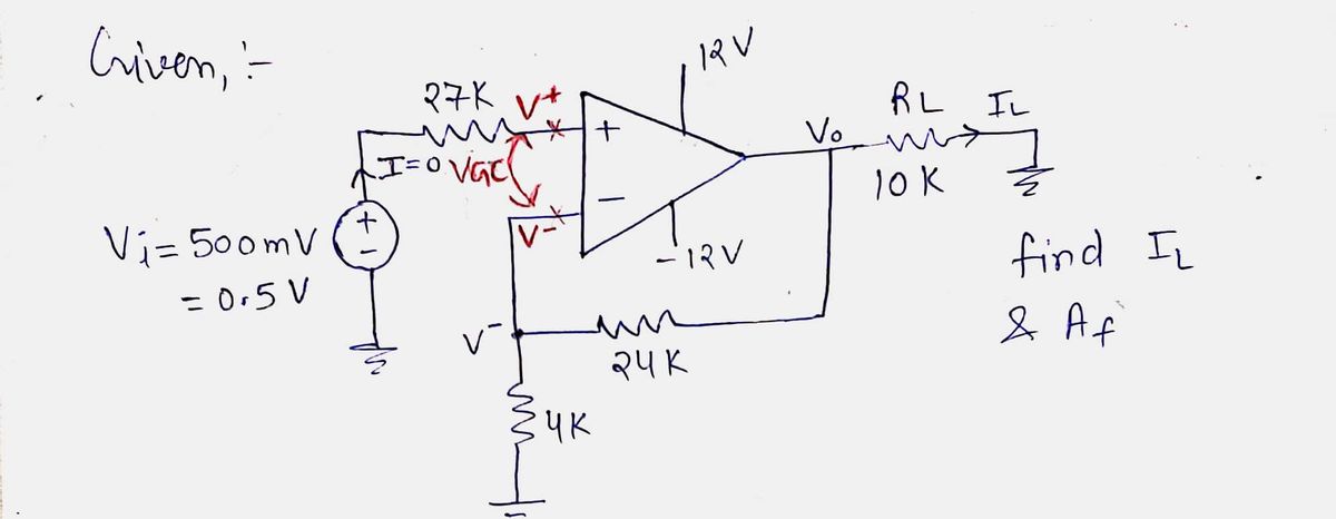
The diagram illustrates an operational amplifier (op-amp) circuit configured to determine the current through a load resistor (\(R_L\)) and to calculate the gain (\(A_F\)). The op-amp is powered by \(+12V\) and \(-12V\) sources.
#### Circuit Components:
1. **Input Voltage Source**: 500 mV connected through a 27 kΩ resistor to the non-inverting terminal (\(+\)) of the op-amp.
2. **Feedback Network**: Composed of a 24 kΩ resistor feeding back to the inverting terminal (\(-\)).
3. **Resistor Network**:
- A 4 kΩ resistor connected between the inverting terminal and ground.
- A load resistor (\(R_L\)) with a value of 10 kΩ is connected to the output of the op-amp.
#### Problem Statement:
- **Objective**: Use circuit analysis to find the current (\(I_L\)) through the load (\(R_L\)). Calculate the gain (\(A_F\)). Assume the op-amp is ideal.
### Analysis Guide:
1. **Ideal Op-Amp Assumptions**:
- Infinite input impedance (no current flows into the input terminals).
- Zero output impedance.
- The voltage difference between the inverting and non-inverting terminals is zero for closed-loop configurations.
2. **Gain Calculation (\(A_F\))**:
- Utilize the feedback network and input conditions to determine the voltage gain of the circuit.
- For inverting or non-inverting setups, apply relevant formulas to calculate the relationship between input and output voltages.
3. **Load Current Calculation (\(I_L\))**:
- Use Ohm's Law (\(V = IR\)) to calculate the current through \(R_L\).
- Ensure proper sign convention based on the assumed direction of currents and the reference node voltages.
This analysis provides the foundational understanding necessary to solve for \(I_L\) and \(A_F\) in this op-amp circuit configuration.
Expert Solution
Step 1

Step by step
Solved in 2 steps with 2 images

Recommended textbooks for you
Introductory Circuit Analysis (13th Edition)
Electrical Engineering
ISBN:
9780133923605
Author:
Robert L. Boylestad
Publisher:
PEARSON

Delmar's Standard Textbook Of Electricity
Electrical Engineering
ISBN:
9781337900348
Author:
Stephen L. Herman
Publisher:
Cengage Learning

Programmable Logic Controllers
Electrical Engineering
ISBN:
9780073373843
Author:
Frank D. Petruzella
Publisher:
McGraw-Hill Education
Introductory Circuit Analysis (13th Edition)
Electrical Engineering
ISBN:
9780133923605
Author:
Robert L. Boylestad
Publisher:
PEARSON
Delmar's Standard Textbook Of Electricity
Electrical Engineering
ISBN:
9781337900348
Author:
Stephen L. Herman
Publisher:
Cengage Learning
Programmable Logic Controllers
Electrical Engineering
ISBN:
9780073373843
Author:
Frank D. Petruzella
Publisher:
McGraw-Hill Education

Fundamentals of Electric Circuits
Electrical Engineering
ISBN:
9780078028229
Author:
Charles K Alexander, Matthew Sadiku
Publisher:
McGraw-Hill Education

Electric Circuits. (11th Edition)
Electrical Engineering
ISBN:
9780134746968
Author:
James W. Nilsson, Susan Riedel
Publisher:
PEARSON

Engineering Electromagnetics
Electrical Engineering
ISBN:
9780078028151
Author:
Hayt, William H. (william Hart), Jr, BUCK, John A.
Publisher:
Mcgraw-hill Education,