Ube V BE UBE -5 V/V 5 V/V 200 V/V 20 V/V )-200 V/V ic Vcc Rc UCE

Introductory Circuit Analysis (13th Edition)
13th Edition
ISBN:9780133923605
Author:Robert L. Boylestad
Publisher:Robert L. Boylestad
Chapter1: Introduction
Section: Chapter Questions
Problem 1P: Visit your local library (at school or home) and describe the extent to which it provides literature...

Related questions
Question
![**BJT Single Transistor Common-Emitter Amplifier**
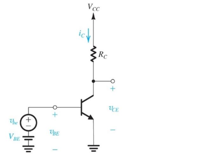
The given problem provides details about a BJT single transistor common-emitter amplifier with the following specifications:
- Supply Voltage (\(V_{CC}\)) = 20 volts
- Collector Current (\(I_C\)) = 5 mA
- Collector Resistor (\(R_C\)) = 1 kΩ
- Thermal Voltage (\(V_T\)) = 25 mV
**Objective:**
Calculate the expected small signal voltage gain (\(v_{ce}/v_{be}\)).
**Circuit Diagram Explanation:**
The diagram illustrates a common-emitter amplifier:
1. **Power Supply:** The circuit is powered by a voltage source, \(V_{CC}\), of 20 volts connected to the collector through the resistor \(R_C\).
2. **Transistor:** The bipolar junction transistor (BJT) is configured with the collector connected to the \(R_C\), the emitter grounded, and the base connected to the input signal.
3. **Input Signal:** The small signal \(v_{be}\) represents the input voltage across the base-emitter junction with a larger DC bias voltage \(V_{BE}\).
4. **Output Voltage:** The output voltage \(v_{ce}\) is taken across the collector-emitter junction.
**Possible Answers:**
The potential answers for the voltage gain are:
- \(-5 \, \text{V/V}\)
- \(5 \, \text{V/V}\)
- \(200 \, \text{V/V}\)
- \(20 \, \text{V/V}\)
- \(-200 \, \text{V/V}\)
- \(-20 \, \text{V/V}\)
**Calculating Voltage Gain:**
The voltage gain (\(A_v\)) for a common-emitter amplifier can be determined using:
\[ A_v = -\frac{R_C}{r_e} \]
Where \(r_e\) is the emitter resistance and can be approximated by:
\[ r_e \approx \frac{V_T}{I_C} \]
Substitute the given values:
\[ r_e \approx \frac{25 \, \text{mV}}{5 \, \text{mA}} = 5 \, \Omega \]
Then, calculate the voltage gain:
\[ A_v = -\frac{1000 \, \Omega}{5 \](/v2/_next/image?url=https%3A%2F%2Fcontent.bartleby.com%2Fqna-images%2Fquestion%2F8b5d3f26-cda5-43e5-8223-bfa02258241c%2F7e6790d8-a991-4440-8745-4bc9a62b5c35%2Flsaymr_processed.jpeg&w=3840&q=75)
Transcribed Image Text:**BJT Single Transistor Common-Emitter Amplifier**
The given problem provides details about a BJT single transistor common-emitter amplifier with the following specifications:
- Supply Voltage (\(V_{CC}\)) = 20 volts
- Collector Current (\(I_C\)) = 5 mA
- Collector Resistor (\(R_C\)) = 1 kΩ
- Thermal Voltage (\(V_T\)) = 25 mV
**Objective:**
Calculate the expected small signal voltage gain (\(v_{ce}/v_{be}\)).
**Circuit Diagram Explanation:**
The diagram illustrates a common-emitter amplifier:
1. **Power Supply:** The circuit is powered by a voltage source, \(V_{CC}\), of 20 volts connected to the collector through the resistor \(R_C\).
2. **Transistor:** The bipolar junction transistor (BJT) is configured with the collector connected to the \(R_C\), the emitter grounded, and the base connected to the input signal.
3. **Input Signal:** The small signal \(v_{be}\) represents the input voltage across the base-emitter junction with a larger DC bias voltage \(V_{BE}\).
4. **Output Voltage:** The output voltage \(v_{ce}\) is taken across the collector-emitter junction.
**Possible Answers:**
The potential answers for the voltage gain are:
- \(-5 \, \text{V/V}\)
- \(5 \, \text{V/V}\)
- \(200 \, \text{V/V}\)
- \(20 \, \text{V/V}\)
- \(-200 \, \text{V/V}\)
- \(-20 \, \text{V/V}\)
**Calculating Voltage Gain:**
The voltage gain (\(A_v\)) for a common-emitter amplifier can be determined using:
\[ A_v = -\frac{R_C}{r_e} \]
Where \(r_e\) is the emitter resistance and can be approximated by:
\[ r_e \approx \frac{V_T}{I_C} \]
Substitute the given values:
\[ r_e \approx \frac{25 \, \text{mV}}{5 \, \text{mA}} = 5 \, \Omega \]
Then, calculate the voltage gain:
\[ A_v = -\frac{1000 \, \Omega}{5 \
Expert Solution
Step 1: we need to determine small signal voltage gain vce/vbe
Given that,
Vcc =20v
Collector current Ic = 5mA
Collector resistor Rc = 1k
Voltage VT = 25mV
Voltage gain format('truetype')%3Bfont-weight%3Anormal%3Bfont-style%3Anormal%3B%7D%3C%2Fstyle%3E%3C%2Fdefs%3E%3Cline%20stroke%3D%22%23000000%22%20stroke-linecap%3D%22square%22%20stroke-width%3D%221%22%20x1%3D%222.5%22%20x2%3D%2229.5%22%20y1%3D%2225.5%22%20y2%3D%2225.5%22%2F%3E%3Ctext%20font-family%3D%22Arial%22%20font-size%3D%2216%22%20font-style%3D%22italic%22%20text-anchor%3D%22middle%22%20x%3D%229.5%22%20y%3D%2215%22%3Ev%3C%2Ftext%3E%3Ctext%20font-family%3D%22Arial%22%20font-size%3D%2212%22%20font-style%3D%22italic%22%20text-anchor%3D%22middle%22%20x%3D%2217.5%22%20y%3D%2220%22%3Ec%3C%2Ftext%3E%3Ctext%20font-family%3D%22Arial%22%20font-size%3D%2212%22%20font-style%3D%22italic%22%20text-anchor%3D%22middle%22%20x%3D%2223.5%22%20y%3D%2220%22%3Ee%3C%2Ftext%3E%3Ctext%20font-family%3D%22Arial%22%20font-size%3D%2216%22%20font-style%3D%22italic%22%20text-anchor%3D%22middle%22%20x%3D%228.5%22%20y%3D%2242%22%3Ev%3C%2Ftext%3E%3Ctext%20font-family%3D%22Arial%22%20font-size%3D%2212%22%20font-style%3D%22italic%22%20text-anchor%3D%22middle%22%20x%3D%2216.5%22%20y%3D%2247%22%3Eb%3C%2Ftext%3E%3Ctext%20font-family%3D%22Arial%22%20font-size%3D%2212%22%20font-style%3D%22italic%22%20text-anchor%3D%22middle%22%20x%3D%2223.5%22%20y%3D%2247%22%3Ee%3C%2Ftext%3E%3Ctext%20font-family%3D%22math17f39f8317fbdb1988ef4c628eb%22%20font-size%3D%2216%22%20text-anchor%3D%22middle%22%20x%3D%2244.5%22%20y%3D%2231%22%3E%3D%3C%2Ftext%3E%3Ctext%20font-family%3D%22Arial%22%20font-size%3D%2216%22%20text-anchor%3D%22middle%22%20x%3D%2257.5%22%20y%3D%2231%22%3E%3F%3C%2Ftext%3E%3C%2Fsvg%3E)

Step by step
Solved in 3 steps with 12 images

Knowledge Booster


Learn more about
Need a deep-dive on the concept behind this application? Look no further. Learn more about this topic, electrical-engineering and related others by exploring similar questions and additional content below.Recommended textbooks for you
Introductory Circuit Analysis (13th Edition)
Electrical Engineering
ISBN:
9780133923605
Author:
Robert L. Boylestad
Publisher:
PEARSON

Delmar's Standard Textbook Of Electricity
Electrical Engineering
ISBN:
9781337900348
Author:
Stephen L. Herman
Publisher:
Cengage Learning

Programmable Logic Controllers
Electrical Engineering
ISBN:
9780073373843
Author:
Frank D. Petruzella
Publisher:
McGraw-Hill Education
Introductory Circuit Analysis (13th Edition)
Electrical Engineering
ISBN:
9780133923605
Author:
Robert L. Boylestad
Publisher:
PEARSON
Delmar's Standard Textbook Of Electricity
Electrical Engineering
ISBN:
9781337900348
Author:
Stephen L. Herman
Publisher:
Cengage Learning
Programmable Logic Controllers
Electrical Engineering
ISBN:
9780073373843
Author:
Frank D. Petruzella
Publisher:
McGraw-Hill Education

Fundamentals of Electric Circuits
Electrical Engineering
ISBN:
9780078028229
Author:
Charles K Alexander, Matthew Sadiku
Publisher:
McGraw-Hill Education

Electric Circuits. (11th Edition)
Electrical Engineering
ISBN:
9780134746968
Author:
James W. Nilsson, Susan Riedel
Publisher:
PEARSON

Engineering Electromagnetics
Electrical Engineering
ISBN:
9780078028151
Author:
Hayt, William H. (william Hart), Jr, BUCK, John A.
Publisher:
Mcgraw-hill Education,