The left-hand section of the torsion member in Figure E6.8 is 2.00 m long, and the right-hand section is 1.00 m long. It is made of an aluminum alloy for which G = 27.1 GPa. Determine the magnitude of T2 if T1 = 350 N•m and the maximum shear stress is 45.0 MPa. Neglect stress concentrations at changes in section. Determine the angle of twist of the free end. The support at the left end prevents rotation of this cross section but does not prevent warping of the cross section. FIGURE E6.8 40 mm 60 mm 30 mm
The left-hand section of the torsion member in Figure E6.8 is 2.00 m long, and the right-hand section is 1.00 m long. It is made of an aluminum alloy for which G = 27.1 GPa. Determine the magnitude of T2 if T1 = 350 N•m and the maximum shear stress is 45.0 MPa. Neglect stress concentrations at changes in section. Determine the angle of twist of the free end. The support at the left end prevents rotation of this cross section but does not prevent warping of the cross section. FIGURE E6.8 40 mm 60 mm 30 mm
Chapter2: Loads On Structures
Section: Chapter Questions
Problem 1P
Related questions
Question
Advanced

Transcribed Image Text:**Torsion Member Analysis**
**Problem Statement:**
The left-hand section of the torsion member in Figure E6.8 is 2.00 meters long, and the right-hand section is 1.00 meter long. It is constructed from an aluminum alloy with a modulus of rigidity \( G \) of 27.1 GPa. The task is to determine the magnitude of \( T_2 \) given that \( T_1 = 350 \, \text{N} \cdot \text{m} \) and that the maximum shear stress is 45.0 MPa. In this problem, neglect stress concentrations at changes in the section. Additionally, determine the angle of twist of the free end. The support at the left end prevents the rotation of this cross-section but allows warping.
**Diagram Description:**
Figure E6.8 illustrates a torsion member. The left section of the bar is 2.00 meters in length with a diameter of 60 mm. The right section is 1.00 meter in length with a reduced diameter of 30 mm. Torque \( T_1 \) acts at the end of the left section, while torque \( T_2 \) acts at the free end of the right section.
The diagram provides dimensions and indicates the positions where the torques are applied. The boundary conditions show that the left end is fixed in terms of rotation but not warping, which means the structure is free to deform axially.
This problem involves calculating the unknown torque \( T_2 \) and the angle of twist using material properties and geometric dimensions provided.
Expert Solution
This question has been solved!
Explore an expertly crafted, step-by-step solution for a thorough understanding of key concepts.
This is a popular solution!
Trending now
This is a popular solution!
Step by step
Solved in 2 steps with 2 images

Follow-up Questions
Read through expert solutions to related follow-up questions below.
Follow-up Question
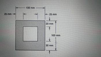
Determine the minimum radius of gyration for the column cross and find the
slenderness ratio of the column.
b) Determine the buckling load for the column.
Take E = 72GPA

Transcribed Image Text:25 mm
100 mm
25 mm
20 mm
T
100 mm
30 mm
Solution
Knowledge Booster
Learn more about
Need a deep-dive on the concept behind this application? Look no further. Learn more about this topic, civil-engineering and related others by exploring similar questions and additional content below.Recommended textbooks for you


Structural Analysis (10th Edition)
Civil Engineering
ISBN:
9780134610672
Author:
Russell C. Hibbeler
Publisher:
PEARSON

Principles of Foundation Engineering (MindTap Cou…
Civil Engineering
ISBN:
9781337705028
Author:
Braja M. Das, Nagaratnam Sivakugan
Publisher:
Cengage Learning


Structural Analysis (10th Edition)
Civil Engineering
ISBN:
9780134610672
Author:
Russell C. Hibbeler
Publisher:
PEARSON

Principles of Foundation Engineering (MindTap Cou…
Civil Engineering
ISBN:
9781337705028
Author:
Braja M. Das, Nagaratnam Sivakugan
Publisher:
Cengage Learning

Fundamentals of Structural Analysis
Civil Engineering
ISBN:
9780073398006
Author:
Kenneth M. Leet Emeritus, Chia-Ming Uang, Joel Lanning
Publisher:
McGraw-Hill Education


Traffic and Highway Engineering
Civil Engineering
ISBN:
9781305156241
Author:
Garber, Nicholas J.
Publisher:
Cengage Learning