The graph below shows the input to the illustrated 4) circuit. On the same graph sketch the output Vout· 0.01 μF Vin Vaut H 16&N 0.5 -0.5 0.002 -0.0015 -0.001 -0.0005 o 0.0005 0.001 0.0015 0.002 Time (s)
The graph below shows the input to the illustrated 4) circuit. On the same graph sketch the output Vout· 0.01 μF Vin Vaut H 16&N 0.5 -0.5 0.002 -0.0015 -0.001 -0.0005 o 0.0005 0.001 0.0015 0.002 Time (s)

Related questions
Question

Transcribed Image Text:4)
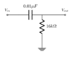
circuit. On the same graph sketch the output Vout:
The graph below shows the input to the illustrated
0.01uF
Vin
Vaut
1
16kN
0.5
-0.5
-1
-0.002 -0.0015 -0.001 -0.0005
0.0005 0.001 0.0015 0.002
Time (s)
Voltage (V)
Expert Solution
Step 1
Given circuit,
Let , be the voltage through the capacitor,
Now the input voltage is always positive,
For output voltage,

Step by step
Solved in 2 steps with 2 images
