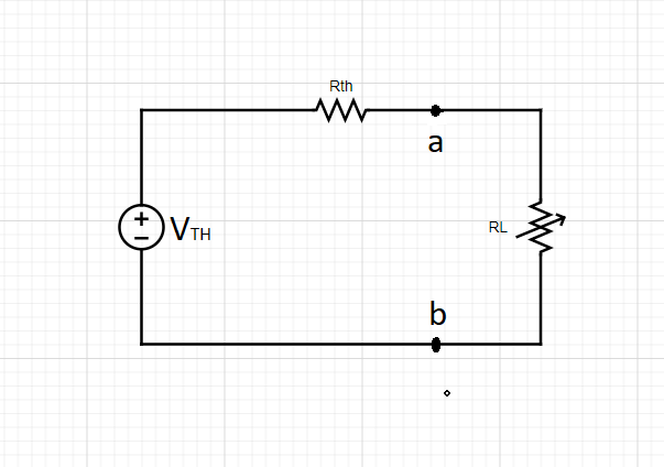
The circuit shown in the figure is equivalent to:

Given data,
finding equivalent circuits across load terminals a and b is done using Thevenin equivalent circuit.
A Thevenin equivalent circuit is used to replace a complex section of a circuit with a voltage source and a resistor. This makes larger circuits easier to create and analyze as the Thevenin equivalent circuit reduces a large number of components to only two. A Thevenin equivalent circuit can also be used to replace a current source.
Thevenin’s theorem states that any linear network with several power sources, resistances, and a variable load can be represented in a much simpler circuit containing a single voltage source (known as Thevenin’s equivalent voltage) in series with a resistance (RTH) (known as Thevenin’s equivalent resistance) and the variable load,

Here, VTH= Open-circuit voltage at the terminals of the load
and RTH = Equivalent resistance measured across the terminals while independent sources are turned off.
Step by step
Solved in 2 steps with 4 images


