Sine-wave generator + 1.0 kHz 1.0 V TISS Voltage across R1, VR Total current, I www 1.0 k Voltage across L, VL Inductive reactance, XL Computed inductance, L Figure 4-Test Circuit 8. The circuit is a series circuit, so the current in the resistor is the identical current that flows through the inductor. Find the voltage across the resistor with the DMM. Apply Ohm's law to the resistor to find the current in the circuit. Record the measured voltage and the computed current in Table 3 in the column labeled Inductor L1. Inductor L1 846mV 846ua 4₁ 628.310 100 mH Inductor L2 Table 3-Measured and Calculated Values
Sine-wave generator + 1.0 kHz 1.0 V TISS Voltage across R1, VR Total current, I www 1.0 k Voltage across L, VL Inductive reactance, XL Computed inductance, L Figure 4-Test Circuit 8. The circuit is a series circuit, so the current in the resistor is the identical current that flows through the inductor. Find the voltage across the resistor with the DMM. Apply Ohm's law to the resistor to find the current in the circuit. Record the measured voltage and the computed current in Table 3 in the column labeled Inductor L1. Inductor L1 846mV 846ua 4₁ 628.310 100 mH Inductor L2 Table 3-Measured and Calculated Values

Introductory Circuit Analysis (13th Edition)
13th Edition
ISBN:9780133923605
Author:Robert L. Boylestad
Publisher:Robert L. Boylestad
Chapter1: Introduction
Section: Chapter Questions
Problem 1P: Visit your local library (at school or home) and describe the extent to which it provides literature...

Related questions
Question
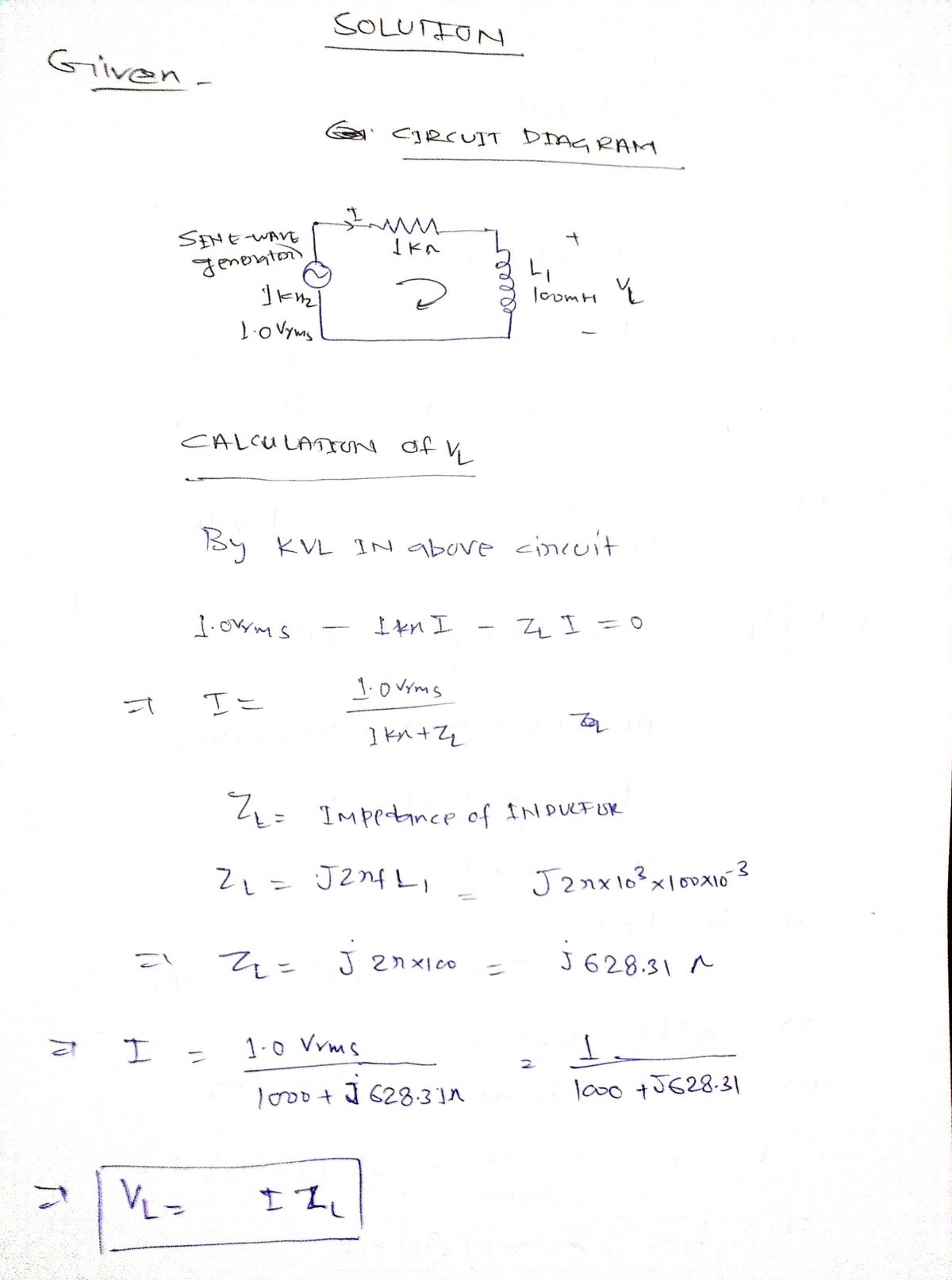
VL and L please

Transcribed Image Text:Sine-wave
generator
+
1.0 kHz
1.0 V TI
Voltage across R1, VR
Total current, I
Voltage across L, VL
Inductive reactance, XL
www
1.0 k
8. The circuit is a series circuit, so the current in the resistor is the identical current that flows through
the inductor. Find the voltage across the resistor with the DMM. Apply Ohm's law to the resistor to
find the current in the circuit. Record the measured voltage and the computed current in Table 3 in
the column labeled Inductor L1.
Computed inductance, L
Figure 4-Test Circuit
Inductor L1
846mV
846ua
4₁
628.310
100 mH
Inductor L2
Table 3-Measured and Calculated Values
Expert Solution
Step 1

Step by step
Solved in 2 steps with 2 images

Knowledge Booster


Learn more about
Need a deep-dive on the concept behind this application? Look no further. Learn more about this topic, electrical-engineering and related others by exploring similar questions and additional content below.Recommended textbooks for you
Introductory Circuit Analysis (13th Edition)
Electrical Engineering
ISBN:
9780133923605
Author:
Robert L. Boylestad
Publisher:
PEARSON

Delmar's Standard Textbook Of Electricity
Electrical Engineering
ISBN:
9781337900348
Author:
Stephen L. Herman
Publisher:
Cengage Learning

Programmable Logic Controllers
Electrical Engineering
ISBN:
9780073373843
Author:
Frank D. Petruzella
Publisher:
McGraw-Hill Education
Introductory Circuit Analysis (13th Edition)
Electrical Engineering
ISBN:
9780133923605
Author:
Robert L. Boylestad
Publisher:
PEARSON
Delmar's Standard Textbook Of Electricity
Electrical Engineering
ISBN:
9781337900348
Author:
Stephen L. Herman
Publisher:
Cengage Learning
Programmable Logic Controllers
Electrical Engineering
ISBN:
9780073373843
Author:
Frank D. Petruzella
Publisher:
McGraw-Hill Education

Fundamentals of Electric Circuits
Electrical Engineering
ISBN:
9780078028229
Author:
Charles K Alexander, Matthew Sadiku
Publisher:
McGraw-Hill Education

Electric Circuits. (11th Edition)
Electrical Engineering
ISBN:
9780134746968
Author:
James W. Nilsson, Susan Riedel
Publisher:
PEARSON

Engineering Electromagnetics
Electrical Engineering
ISBN:
9780078028151
Author:
Hayt, William H. (william Hart), Jr, BUCK, John A.
Publisher:
Mcgraw-hill Education,