) Show the and compute the K . followine systan is type 1 K Cas ob] Ro
) Show the and compute the K . followine systan is type 1 K Cas ob] Ro

Introductory Circuit Analysis (13th Edition)
13th Edition
ISBN:9780133923605
Author:Robert L. Boylestad
Publisher:Robert L. Boylestad
Chapter1: Introduction
Section: Chapter Questions
Problem 1P: Visit your local library (at school or home) and describe the extent to which it provides literature...

Related questions
Question
![### Problem Statement
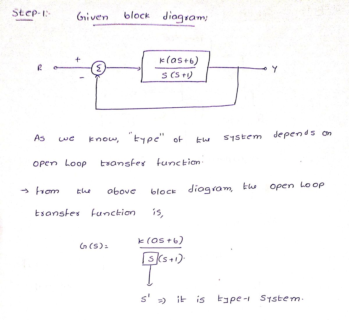
1) Show the following system is type 1 and compute the \( K_v \).
### System Diagram
The diagram is a block diagram of a control system. It consists of the following components:
- **Input \( R \)**: The reference input to the system.
- **Summation Block \( \Sigma \)**: It takes the difference between the input \( R \) and the feedback signal.
- **Transfer Function Block**: This block has the transfer function:
\[
\frac{K(as + b)}{s(s+1)}
\]
where \( K \), \( a \), and \( b \) are constants, and \( s \) is the Laplace variable.
- **Output \( Y \)**: The system output.
### Feedback Loop
The system includes a feedback loop where the output \( Y \) is fed back into the summation block to be subtracted from the input \( R \).
This block diagram represents a control system with a feedback loop. To demonstrate that the system is type 1, analyze the transfer function and compute the velocity error constant \( K_v \).](/v2/_next/image?url=https%3A%2F%2Fcontent.bartleby.com%2Fqna-images%2Fquestion%2Fb5312a15-860e-407c-ae9e-8729c86c8316%2F09150984-e00c-4fb4-9e29-baa29de6027b%2Fwei0yjeg_processed.png&w=3840&q=75)
Transcribed Image Text:### Problem Statement
1) Show the following system is type 1 and compute the \( K_v \).
### System Diagram
The diagram is a block diagram of a control system. It consists of the following components:
- **Input \( R \)**: The reference input to the system.
- **Summation Block \( \Sigma \)**: It takes the difference between the input \( R \) and the feedback signal.
- **Transfer Function Block**: This block has the transfer function:
\[
\frac{K(as + b)}{s(s+1)}
\]
where \( K \), \( a \), and \( b \) are constants, and \( s \) is the Laplace variable.
- **Output \( Y \)**: The system output.
### Feedback Loop
The system includes a feedback loop where the output \( Y \) is fed back into the summation block to be subtracted from the input \( R \).
This block diagram represents a control system with a feedback loop. To demonstrate that the system is type 1, analyze the transfer function and compute the velocity error constant \( K_v \).
Expert Solution
Step 1

Step by step
Solved in 2 steps with 2 images

Recommended textbooks for you
Introductory Circuit Analysis (13th Edition)
Electrical Engineering
ISBN:
9780133923605
Author:
Robert L. Boylestad
Publisher:
PEARSON

Delmar's Standard Textbook Of Electricity
Electrical Engineering
ISBN:
9781337900348
Author:
Stephen L. Herman
Publisher:
Cengage Learning

Programmable Logic Controllers
Electrical Engineering
ISBN:
9780073373843
Author:
Frank D. Petruzella
Publisher:
McGraw-Hill Education
Introductory Circuit Analysis (13th Edition)
Electrical Engineering
ISBN:
9780133923605
Author:
Robert L. Boylestad
Publisher:
PEARSON
Delmar's Standard Textbook Of Electricity
Electrical Engineering
ISBN:
9781337900348
Author:
Stephen L. Herman
Publisher:
Cengage Learning
Programmable Logic Controllers
Electrical Engineering
ISBN:
9780073373843
Author:
Frank D. Petruzella
Publisher:
McGraw-Hill Education

Fundamentals of Electric Circuits
Electrical Engineering
ISBN:
9780078028229
Author:
Charles K Alexander, Matthew Sadiku
Publisher:
McGraw-Hill Education

Electric Circuits. (11th Edition)
Electrical Engineering
ISBN:
9780134746968
Author:
James W. Nilsson, Susan Riedel
Publisher:
PEARSON

Engineering Electromagnetics
Electrical Engineering
ISBN:
9780078028151
Author:
Hayt, William H. (william Hart), Jr, BUCK, John A.
Publisher:
Mcgraw-hill Education,