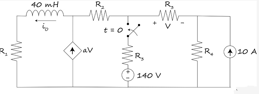
R₁ ww K₁ = K₂= K3 = 40 mH io av t = 0 WW ww + 140 V R₂ 10 A The switch has been open for a long time and closes at t = 0. Given R1 = 80 S2, R2 = 160 N, R3 = 240 S2, R4 = 320 S, a = A/V determine the coefficients for the current i = K₁ + K₂e-K3¹ A.
R₁ ww K₁ = K₂= K3 = 40 mH io av t = 0 WW ww + 140 V R₂ 10 A The switch has been open for a long time and closes at t = 0. Given R1 = 80 S2, R2 = 160 N, R3 = 240 S2, R4 = 320 S, a = A/V determine the coefficients for the current i = K₁ + K₂e-K3¹ A.

Introductory Circuit Analysis (13th Edition)
13th Edition
ISBN:9780133923605
Author:Robert L. Boylestad
Publisher:Robert L. Boylestad
Chapter1: Introduction
Section: Chapter Questions
Problem 1P: Visit your local library (at school or home) and describe the extent to which it provides literature...

Related questions

Question
Please answer in typing format solution
I will like it please reply
Please it's emergency

Transcribed Image Text:### Circuit Analysis Problem
**Circuit Description:**
- **Inductor:** 40 mH positioned at the left top corner.
- **Current (`i₀`):** Flows leftward through the inductor.
- **Resistors:**
- \( R_1 \) located on the left side.
- \( R_2 \) placed vertically after the dependent voltage source.
- \( R_3 \) horizontally near the switch.
- \( R_4 \) in series with a 10 A current source on the right.
- **Dependent Voltage Source:**
- Denoted as \( aV \), where \( a = 0.7 \) A/V.
- **Independent Voltage Source:**
- \( 140 \) V located vertically after the switch.
- **Independent Current Source:** 10 A to the right side of the circuit.
- **Switch:**
- Initially open, closes at \( t = 0 \).
**Given Values:**
- \( R_1 = 80 \, \Omega \)
- \( R_2 = 160 \, \Omega \)
- \( R_3 = 240 \, \Omega \)
- \( R_4 = 320 \, \Omega \)
**Objective:**
Determine the coefficients for the current \( i₀ = K_1 + K_2 e^{-K_3 t} \, A \).
**Coefficients to Determine:**
- \( K_1 = \)
- \( K_2 = \)
- \( K_3 = \)
**Instructions:**
Using the given circuit values and the relationship provided for \( i₀ \), solve for the coefficients \( K_1 \), \( K_2 \), and \( K_3 \) by applying appropriate circuit analysis techniques, such as Kirchhoff’s laws, node-voltage analysis, or mesh-current analysis.
### Diagram Explanation:
- **Positioning:** The circuit components are laid out from left to right, with the inductance and switch prominently marked.
- **Flow:** Current \( i₀ \) flows counterclockwise around the loop when the switch closes.
- **Dependency:** The voltage across the dependent source is multiplied by a factor \( a \).
### Analyze & Solve:
- Break down each loop and apply laws of circuits for thorough analysis.
- Use the given resistance values, current, and voltage sources to formulate equations
Expert Solution
Step 1: Given

Step by step
Solved in 7 steps with 25 images

Knowledge Booster


Learn more about
Need a deep-dive on the concept behind this application? Look no further. Learn more about this topic, electrical-engineering and related others by exploring similar questions and additional content below.Recommended textbooks for you
Introductory Circuit Analysis (13th Edition)
Electrical Engineering
ISBN:
9780133923605
Author:
Robert L. Boylestad
Publisher:
PEARSON

Delmar's Standard Textbook Of Electricity
Electrical Engineering
ISBN:
9781337900348
Author:
Stephen L. Herman
Publisher:
Cengage Learning

Programmable Logic Controllers
Electrical Engineering
ISBN:
9780073373843
Author:
Frank D. Petruzella
Publisher:
McGraw-Hill Education
Introductory Circuit Analysis (13th Edition)
Electrical Engineering
ISBN:
9780133923605
Author:
Robert L. Boylestad
Publisher:
PEARSON
Delmar's Standard Textbook Of Electricity
Electrical Engineering
ISBN:
9781337900348
Author:
Stephen L. Herman
Publisher:
Cengage Learning
Programmable Logic Controllers
Electrical Engineering
ISBN:
9780073373843
Author:
Frank D. Petruzella
Publisher:
McGraw-Hill Education

Fundamentals of Electric Circuits
Electrical Engineering
ISBN:
9780078028229
Author:
Charles K Alexander, Matthew Sadiku
Publisher:
McGraw-Hill Education

Electric Circuits. (11th Edition)
Electrical Engineering
ISBN:
9780134746968
Author:
James W. Nilsson, Susan Riedel
Publisher:
PEARSON

Engineering Electromagnetics
Electrical Engineering
ISBN:
9780078028151
Author:
Hayt, William H. (william Hart), Jr, BUCK, John A.
Publisher:
Mcgraw-hill Education,