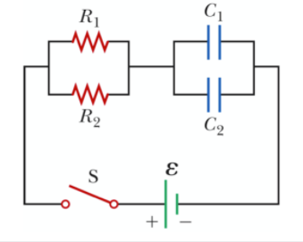
Q 2. The circuit in the diagram R1 contains R1 = 2 kN, R2 = 3kN, C1 = 2 µF, C2 = 3 µF and ɛ = on both capacitors individually as a function of 120 V. Calculate the charges time if the switch is closed at t 0 assum- ing that the capacitors have been uncharged for R2 C2 t < 0. S +
Q 2. The circuit in the diagram R1 contains R1 = 2 kN, R2 = 3kN, C1 = 2 µF, C2 = 3 µF and ɛ = on both capacitors individually as a function of 120 V. Calculate the charges time if the switch is closed at t 0 assum- ing that the capacitors have been uncharged for R2 C2 t < 0. S +
Related questions
Question
question attached below

Transcribed Image Text:Q 2.
The circuit in the diagram
R1
contains R1 = 2 kN, R2 = 3kN, C1 = 2 µF,
C2 = 3 µF and ɛ =
on both capacitors individually as a function of
120 V. Calculate the charges
time if the switch is closed at t
0 assum-
ing that the capacitors have been uncharged for
R2
C2
t < 0.
S
+
Expert Solution
Step 1
Given:
The circuit diagram is as follows.

Introduction:
An RC circuit is a circuit with both a resistor (R) and a capacitor (C). RC circuits are frequent element in electronic devices. They also play an important role in the transmission of electrical signals in nerve cells. A capacitor can store energy and a resistor placed in series with it will control the rate at which it charges or discharges. This produces a characteristic time dependence that turns out to be exponential.
Step by step
Solved in 3 steps with 1 images
