Problems 767 10 k2 D2 Us 2 k2 4.7 k2 -1vF Figure P12.103 10|1. 2R D, A Аз Us Figure P12.107
The triangular waveform is applied to the circuit in. P12.107. Draw the corresponding output waveform
![Problems
767
10 k2
D2
Us
2 k2
4.7 k2
-1vF
Figure P12.103
10|1.](/v2/_next/image?url=https%3A%2F%2Fcontent.bartleby.com%2Fqna-images%2Fquestion%2F40cc1a9b-45d2-4b41-86dc-a8d0707ac626%2F049935c3-498f-4f32-af78-c3a30b60670f%2F2m6af4o.png&w=3840&q=75)
![2R
D,
A
Аз
Us
Figure P12.107](/v2/_next/image?url=https%3A%2F%2Fcontent.bartleby.com%2Fqna-images%2Fquestion%2F40cc1a9b-45d2-4b41-86dc-a8d0707ac626%2F049935c3-498f-4f32-af78-c3a30b60670f%2Fmk97p8t.png&w=3840&q=75)
![](/static/compass_v2/shared-icons/check-mark.png)
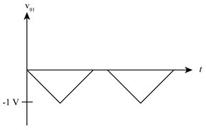
In the above circuit, first part of op-amp circuit is half wave rectifier with inverted output, the input triangular waveform is applying to the circuit, output of the positive half cycle (v01) will be equal to (-vs) and the output of negative half cycle will be zero.
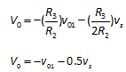
In the above circuit, second part of op-amp circuit is adder amplifier which is used to combine the voltage present on two or more inputs in a single, final output voltage of the triangular waveform is the sum of first inverted output voltage and inverted input voltage.
Output voltage of second op-amp circuit at (R2=R3)
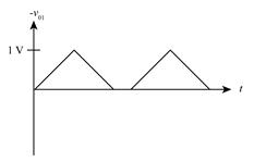
Output voltage waveform for both v01 and vs
Step by step
Solved in 3 steps with 5 images
![Blurred answer](/static/compass_v2/solution-images/blurred-answer.jpg)
![Introductory Circuit Analysis (13th Edition)](https://www.bartleby.com/isbn_cover_images/9780133923605/9780133923605_smallCoverImage.gif)
![Delmar's Standard Textbook Of Electricity](https://www.bartleby.com/isbn_cover_images/9781337900348/9781337900348_smallCoverImage.jpg)
![Programmable Logic Controllers](https://www.bartleby.com/isbn_cover_images/9780073373843/9780073373843_smallCoverImage.gif)
![Fundamentals of Electric Circuits](https://www.bartleby.com/isbn_cover_images/9780078028229/9780078028229_smallCoverImage.gif)
![Electric Circuits. (11th Edition)](https://www.bartleby.com/isbn_cover_images/9780134746968/9780134746968_smallCoverImage.gif)
![Engineering Electromagnetics](https://www.bartleby.com/isbn_cover_images/9780078028151/9780078028151_smallCoverImage.gif)