Problem_#03] The input waveform below is applied to a two bit full-adder. Determine the output waveform for the sum and carry out. A₁ A₂ B₁ B₂ Cin
Problem_#03] The input waveform below is applied to a two bit full-adder. Determine the output waveform for the sum and carry out. A₁ A₂ B₁ B₂ Cin

Introductory Circuit Analysis (13th Edition)
13th Edition
ISBN:9780133923605
Author:Robert L. Boylestad
Publisher:Robert L. Boylestad
Chapter1: Introduction
Section: Chapter Questions
Problem 1P: Visit your local library (at school or home) and describe the extent to which it provides literature...

Related questions
Question

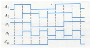
Transcribed Image Text:**Problem #03:** The input waveform below is applied to a two-bit full-adder. Determine the output waveform for the sum and carry out.
_Image Explanation:_
The graph shows waveform inputs labeled \(A_1\), \(A_2\), \(B_1\), \(B_2\), and \(C_{\text{in}}\). These inputs are digital signals, as indicated by the square waveforms, which will be used by the full-adder to produce sums and carry outputs.
---
**Problem #04:** Find the output of the parallel adder shown below.
_Image Explanation:_
The diagram features a series of full-adder blocks labeled with inputs \(A\), \(B\), and \(C_{\text{in}}\), and outputs \(C_{\text{out}}\) (carry out) and \(\Sigma\) (sum). The input bits are displayed on top: 1, 0, 0, 1, 0, 1, 1, and 1, heading into each respective full-adder from left to right, labeled \(\Sigma_6\) to \(\Sigma_1\). Each adder takes its respective inputs and produces the sum and carry outputs according to the full-adder logic.
Expert Solution
Step 1: what is given and what to do:
Given:
input waveforms for a two bit full adder,
we need to find the output waveforms for sum and carry.

Step by step
Solved in 3 steps with 2 images

Knowledge Booster


Learn more about
Need a deep-dive on the concept behind this application? Look no further. Learn more about this topic, electrical-engineering and related others by exploring similar questions and additional content below.Recommended textbooks for you
Introductory Circuit Analysis (13th Edition)
Electrical Engineering
ISBN:
9780133923605
Author:
Robert L. Boylestad
Publisher:
PEARSON

Delmar's Standard Textbook Of Electricity
Electrical Engineering
ISBN:
9781337900348
Author:
Stephen L. Herman
Publisher:
Cengage Learning

Programmable Logic Controllers
Electrical Engineering
ISBN:
9780073373843
Author:
Frank D. Petruzella
Publisher:
McGraw-Hill Education
Introductory Circuit Analysis (13th Edition)
Electrical Engineering
ISBN:
9780133923605
Author:
Robert L. Boylestad
Publisher:
PEARSON
Delmar's Standard Textbook Of Electricity
Electrical Engineering
ISBN:
9781337900348
Author:
Stephen L. Herman
Publisher:
Cengage Learning
Programmable Logic Controllers
Electrical Engineering
ISBN:
9780073373843
Author:
Frank D. Petruzella
Publisher:
McGraw-Hill Education

Fundamentals of Electric Circuits
Electrical Engineering
ISBN:
9780078028229
Author:
Charles K Alexander, Matthew Sadiku
Publisher:
McGraw-Hill Education

Electric Circuits. (11th Edition)
Electrical Engineering
ISBN:
9780134746968
Author:
James W. Nilsson, Susan Riedel
Publisher:
PEARSON

Engineering Electromagnetics
Electrical Engineering
ISBN:
9780078028151
Author:
Hayt, William H. (william Hart), Jr, BUCK, John A.
Publisher:
Mcgraw-hill Education,