Problem 5-4. Find the value of the load resistance R₁ in figure P5.16 which will dissipate maximum power. Find the power delivered to the load resistance when it is set to this value. 4ΚΩ R₁ ΣΚΩ 1ΚΩ 2ix ↑ 6ΚΩ 2mA 2V 4V 3ΚΩ www
Problem 5-4. Find the value of the load resistance R₁ in figure P5.16 which will dissipate maximum power. Find the power delivered to the load resistance when it is set to this value. 4ΚΩ R₁ ΣΚΩ 1ΚΩ 2ix ↑ 6ΚΩ 2mA 2V 4V 3ΚΩ www

Introductory Circuit Analysis (13th Edition)
13th Edition
ISBN:9780133923605
Author:Robert L. Boylestad
Publisher:Robert L. Boylestad
Chapter1: Introduction
Section: Chapter Questions
Problem 1P: Visit your local library (at school or home) and describe the extent to which it provides literature...

Related questions

Question
Solve

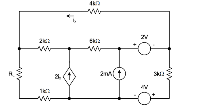
Transcribed Image Text:**Problem 5-4.** Find the value of the load resistance \( R_L \) in figure P5.16 which will dissipate maximum power. Find the power delivered to the load resistance when it is set to this value.
**Diagram Explanation:**
The circuit diagram includes:
- A load resistor \( R_L \).
- Four resistors with resistances: 4kΩ, 2kΩ, 6kΩ, and 3kΩ.
- A 1kΩ resistor in series with the load resistor \( R_L \).
- Two voltage sources: 2V (positive on the left) and 4V (positive on the bottom).
- A current source providing 2mA.
- A current-dependent current source positioned vertically, with 2iₓ, where iₓ is the current through the 4kΩ resistor.
### Steps to Solve:
1. **Determine Maximum Power Transfer:**
The load resistance \( R_L \) will dissipate maximum power when \( R_L \) equals the Thevenin resistance of the network viewed from the terminals of \( R_L \).
2. **Calculate Thevenin Equivalent:**
- Remove \( R_L \) from the circuit.
- Calculate the open-circuit voltage and the equivalent resistance seen from \( R_L \)'s terminals.
3. **Power Calculation:**
Use \( P = \frac{V_{th}^2}{4R_{th}} \) to find the power delivered to \( R_L \), where \( V_{th} \) is the Thevenin voltage and \( R_{th} \) is the Thevenin resistance.
By solving these steps, you can determine both the value for \( R_L \) that maximizes power dissipation, and the amount of power delivered when \( R_L \) is at this value.
Expert Solution
Step 1: State the given data,
The given circuit is
we need to find the value of the load resistance so that maximum power will transfer to it and finding the maximum power.

Trending now
This is a popular solution!

Step by step
Solved in 5 steps with 4 images

Knowledge Booster


Learn more about
Need a deep-dive on the concept behind this application? Look no further. Learn more about this topic, electrical-engineering and related others by exploring similar questions and additional content below.Recommended textbooks for you
Introductory Circuit Analysis (13th Edition)
Electrical Engineering
ISBN:
9780133923605
Author:
Robert L. Boylestad
Publisher:
PEARSON

Delmar's Standard Textbook Of Electricity
Electrical Engineering
ISBN:
9781337900348
Author:
Stephen L. Herman
Publisher:
Cengage Learning

Programmable Logic Controllers
Electrical Engineering
ISBN:
9780073373843
Author:
Frank D. Petruzella
Publisher:
McGraw-Hill Education
Introductory Circuit Analysis (13th Edition)
Electrical Engineering
ISBN:
9780133923605
Author:
Robert L. Boylestad
Publisher:
PEARSON
Delmar's Standard Textbook Of Electricity
Electrical Engineering
ISBN:
9781337900348
Author:
Stephen L. Herman
Publisher:
Cengage Learning
Programmable Logic Controllers
Electrical Engineering
ISBN:
9780073373843
Author:
Frank D. Petruzella
Publisher:
McGraw-Hill Education

Fundamentals of Electric Circuits
Electrical Engineering
ISBN:
9780078028229
Author:
Charles K Alexander, Matthew Sadiku
Publisher:
McGraw-Hill Education

Electric Circuits. (11th Edition)
Electrical Engineering
ISBN:
9780134746968
Author:
James W. Nilsson, Susan Riedel
Publisher:
PEARSON

Engineering Electromagnetics
Electrical Engineering
ISBN:
9780078028151
Author:
Hayt, William H. (william Hart), Jr, BUCK, John A.
Publisher:
Mcgraw-hill Education,